audi Workshop Repair Guides

Audi Workshop Service and Repair Manuals

Check lambda probe and lambda control downstream of catalytic converter > < Check lambda probe ageing upstream of catalytic converter
Motronic Fuel Injection and Ignition System (4-cyl) Turbo
Checking lambda control
Lambda probe heater Check -Z19 for lambda probe upstream of catalytic converter
 
G24-0020

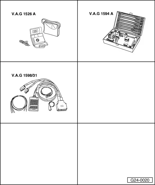
Special tools and workshop equipment required

  • ◆ V.A.G 1526 A
  • ◆ V.A.G 1594 A
  • ◆ V.A.G 1598/31

Test requirements:

  • ● Coolant temperature at least 80 °C.
 
A24-0392
  • ● Fuse for Lambda probe heating OK.

=> Current Flow Diagrams, Electrical Fault-Finding and Fitting Locations

Test sequence

  • ‒ → Unplug 6-pin connector (black) -2- to lambda probe upstream of catalytic converter -G39.

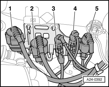
Note:

To gain access to the connector screw out coolant expansion tank bolts and swivel expansion tank aside. Fuel hoses remain connected.

 
A24-0336
  • ‒ → Connect multimeter between contacts 3 and 4 to measure resistance.
    • ‒ Specified value at room temperature 2.5...10 ω

If specified value is not attained:

  • ‒ Replace the lambda probe 1 upstream of catalytic converter
    -G39.

If specified value is attained:

  • ‒ Check the voltage supply to the Lambda probe heating.
 
A24-0139

Checking voltage supply for lambda probe heating

  • ‒ → Connect multimeter between contacts 3 and 4 to measure voltage.
  • ‒ Start the engine.
    • ‒ Specified value: approx. battery voltage

Note:

Points at which Lambda probe heating is switched on and off by engine control unit can be observed in "Reading measured value block" function, display group number 041 and display zone 2.

 
A24-0139

If no voltage is present:

  • ‒ → Connect multimeter as follows to measure voltage.

Connector
contact

Measure to

3 (positive)

Vehicle earth

  • ‒ Operate starter briefly.
    • ‒ Specified value: approx. battery voltage

If no voltage is present:

  • ‒ Check the wiring from contact 3 on the connector via the fuse to the fuel pump relay for an open circuit:

=> Current Flow Diagrams, Electrical Fault-Finding and Fitting Locations

If voltage supply is OK:

 
A24-0139
  • ‒ → Connect multimeter as follows to measure voltage:

Connector
contact

Measure to

4 (earth actuation by engine control unit)

Battery positive

  • ‒ Start the engine.
    • ‒ Specified value: approx. battery voltage

Note:

Points at which Lambda probe heating is switched on and off by engine control unit can be observed in "Reading measured value block" function, display group number 041 and display zone 2.

  • ‒ Switch ignition off.

If no voltage is present:

  • ‒ Connect the V.A.G 1598/31 test box to wiring harness leading to engine control unit; the engine control unit should not be connected .
 
A24-0139
  • ‒ → Check for open circuit in the following wiring connections:

Connector
contact

Test box V.A.G 1598/31
Socket

4

5

  • ‒ Rectify open circuit, if necessary

=> Current Flow Diagrams, Electrical Fault-Finding and Fitting Locations

If wiring is OK but there is no earth supply for the Lambda probe heating:

  • ‒ Fit a new engine control unit => Page 24-23.

Check lambda probe and lambda control downstream of catalytic converter > < Check lambda probe ageing upstream of catalytic converter