audi Workshop Repair Guides

Audi Workshop Service and Repair Manuals

Ignition system, glow plug system > < Check the data exchange between engine control unit and other CAN-control units
Motronic Fuel Injection and Ignition System (4-cyl) Turbo
Vacuum diagram
Vacuum diagram
 
A24-0362
  • Activated charcoal filter
  • Solenoid valve 1 for activated charcoal filter -N80
  • Non return valve for ACF
    • ◆ Between ACF container and intake pipe upstream of exhaust turbocharger
    • ◆ Note installation position (light side/ dark side) as shown in Fig, arrow faces in direction of flow
  • Air cleaner
    • ◆ With air mass meter -G70
  • Turbocharger
  • Combi valve for secondary air inlet
 
A24-0362
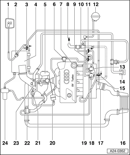
  • Fuel pressure regulator
  • To brake servo
  • Non-return valve
    • ◆ Between brake servo and intake pipe
    • ◆ Note installation position (light side/ dark side) as shown in Fig, arrow faces in direction of flow
  • Suction jet pump
  • Non-return valve
    • ◆ Between brake servo and intake pipe
    • ◆ Note installation position (light side/ dark side) as shown in Fig, arrow faces in direction of flow
  • Vacuum reservoir
    • ◆ Location: In front left wheel housing beneath wheel housing liner
 
A24-0362
  • Checking secondary air inlet valve
    -N112
    • ◆ Location: underneath the intake pipe
  • Crankcase breather
  • Non-return valve
    • ◆ Between ACF container and intake pipe
    • ◆ Note installation position (light side/ dark side) as shown in Fig, arrow faces in direction of flow
  • Charge air cooler
    • ◆ With boost pressure sender -G31
  • Throttle valve control unit -J338
  • Air recirculation valve for turbocharger -N249
    • ◆ Location: underneath the intake pipe
 
A24-0362
  • Intake manifold
    • ◆ With intake air temperature sender -G42
  • Vaccum unit for boost pressure control
    • ◆ When the combination valve opens the mechanical air pressure control valve in the exhaust turbocharger is opened and the secondary air is directly guided to the catalytic converter past the exhaust turbocharger
  • Boost pressure control solenoid valve -N75
  • Mechanical air recirculation valve
  • Crankcase breather pressure regulating valve
  • Secondary air pump motor -V101

Ignition system, glow plug system > < Check the data exchange between engine control unit and other CAN-control units