
A4 Mk1
| → Indicated on display: |
|
||
|
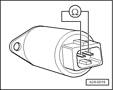
Upon actuation of camshaft timing control, the valve should give a clearly audible click. If the valve does not click, then switch the ignition off.
|
 |
|
Specification: 12 ... 16 ω.
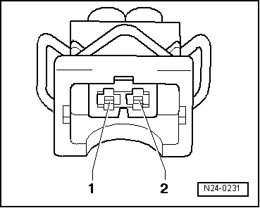
Check power supply to valve for camshaft timing control -N205 |
 |
|
The diode test lamp should light up. If the diode test lamp does not light up, carry out the following tests:
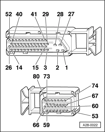
=> "Current Flow Diagrams, Electrical Fault Finding and Fitting Locations" binder
|
|
|
|
Checking actuation of camshaft timing control
|
| → Indicated on display: |
|
||
|
The diode test lamp should flash on and off upon actuation of camshaft adjustment.
|
 |
|
=> "Current Flow Diagrams, Electrical Fault Finding and Fitting Locations" binder
=> "Current Flow Diagrams, Electrical Fault Finding and Fitting Locations" binder
|