audi Workshop Repair Guides

Audi Workshop Service and Repair Manuals

Checking camshaft timing control > < Checking knock sensors
Motronic Fuel Injection and ignition system (4-cyl.) 07.96ä
Checking knock control system
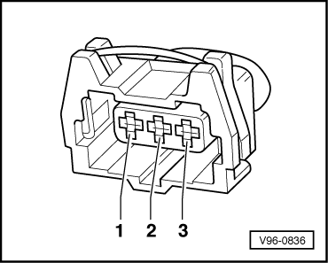
Checking Hall sender

The Hall sender indicates the ignition position for cylinder 1.

If the Hall sender fails to function, the knock control is switched off and the ignition timing is retarded slightly because the signals can no longer be assigned to the cylinders.

Even without a signal from the Hall sender, the engine will continue to run and can also be restarted.

    • ‒ With the twin spark ignition system an ignition spark is produced for each cylinder after every engine revolution, and not after alternate revolutions as is normally the case.
    • ‒ The fact that the control unit is out of phase by one engine revolution does not have any noticeable effect on the injection system. If this happens, the fuel is injected "upstream" (before the closed inlet valve) instead of while the inlet valve is open. This has only a minor influence on the quality of the air/fuel mixture.

Note on signal testing with an oscilloscope:

The centre point of the window of the Hall sender must lie on the third falling flank of the engine speed signal after the reference mark gap.

 
V96-0836
  • ‒ Push back the rubber sleeve on the Hall sender connector.
  • ‒ → Connect the V.A.G 1527 diode test lamp to contacts 1 and 2 on the Hall sender connector from behind (the connector remains attached to the Hall sender).

Note:

Receptacles are numbered accordingly on the back of the connector.

  • ‒ Operate the starter for a few seconds.
  • The diode test lamp must flash briefly on each second engine revolution.

If the diode test lamp does not flash:

 
V96-0836
  • ‒ Unplug the connector from the Hall sender.
  • ‒ Switch the ignition on.
  • ‒ → Connect multimeter to measure voltage at contacts 1 and 3 of the connector:
  • Specification: 4.5 ... 5.5 V
  • ‒ Connect multimeter to measure voltage at contacts 2 and 3 of the connector:
  • Specification: approx. battery voltage

If the specification is obtained:

  • ‒ Renew Hall sender (G40).

If the specification is not obtained:

  • ‒ Switch off ignition.
  • ‒ Connect test box V.A.G 1598/22 to wiring harness for engine control unit
    .
 
V96-0836

The following wiring connections should be checked for open circuits and/or short to positive or negative.

3-pin connector on the wiring harness contact.

Test box V.A.G 1598/22, socket

1

62

2

76

3

67

  • ‒ Rectify any open/short circuit as necessary.

Checking camshaft timing control > < Checking knock sensors