audi Workshop Repair Guides

Audi Workshop Service and Repair Manuals

Checking output stages for ignition coils > < Technical data for ignition system
Motronic Fuel Injection and Ignition System (6-cyl. Turbo)
Checking ignition system
Checking ignition coils

Note:

Misfiring is monitored by the self-diagnosis for vehicles which fulfil the emission standard EU III. This means that a cylinder which is not firing is stored in the fault memory together with the appropriate cylinder number. The advantage of this is that fault finding can be initiated from e.g. a specific cylinder in the case of fault. Therefore interrogate the engine control unit before starting this test.

Test conditions

  • ● No faults relating to injector(s) stored

Identify an inoperative or misfiring cylinder as follows:

  • ‒ Disconnect connectors from the injectors in sequence with the engine running, and observe how the engine runs.
  • or
  • ‒ Compare the spark plugs of all cylinders with each other and check for soot on the electrodes.

If the defective cylinder has been identified:

  • ‒ Connect multimeter (resistance measurement range) to spark plug connector.

Note:

The spark plug connector can be unplugged from the ignition coil.

  • Specification: approx. 2 kω

If specification is not attained:

  • ‒ Replace the spark plug connector.

If specification is attained:

  • ‒ Replace the spark plug of the defective cylinder with one from another cylinder. First perform visual inspection of spark plug for possible damage, e.g. cracks in ceramic body of spark plug.
  • ‒ If the fault now occurs at the other cylinder, renew the spark plug.

If the fault remains in the same cylinder:

  • ‒ Replace the ignition coil from the defective cylinder with one from another cylinder.First perform visual inspection of ignition coil for damage (ignition coil may have cracked (micro crack) or split open).
  • ‒ If the fault now occurs at the other cylinder, renew the ignition coil.

If the fault remains in the same cylinder:

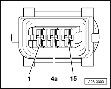
  • ‒ Unplug the connector from the ignition coil.
 
A28-0003
  • ‒ → Check earth connection from contact 4a to engine earth for open circuit or short to positive.

=> Current Flow Diagrams, Electrical Fault-Finding and Fitting Locations

  • ‒ Rectify any open/short circuit as necessary.

If the earth connection is OK:

  • ‒ → Connect multimeter between earth and contact 15 on the connector to measure the voltage.
  • ‒ Disconnect injector of cylinder to be tested.
  • ‒ Operate starter.
  • Specification on multimeter: approx. battery voltage

If specification is not attained:

  • ‒ Check the wiring connections.

=> Current Flow Diagrams, Electrical Fault-Finding and Fitting Locations

If specification is attained:

  • ‒ Disconnect 3-pin connectors on output stages for ignition coils; Installation locations overview =>Page 24-5.
  • ‒ Then connect diode test lamp to the 3-pin connectors of both output stages.
 
V96-0836
  • ‒ → Connect the V.A.G 1527 diode test lamp to the following contacts on the output stage connectors: Then actuate the starter for a few seconds.

3-pin connector on wiring harness, Contact

Specification on actuation of starter

1 + earth

Diode test lamp should

2 + earth

light up

3 + earth

If specifications are not attained:

  • ‒ Switch ignition off.
 
V96-0836

The following wiring connections are to be checked for open circuits and/or short to positive or negative.

3-pin connector on the power stage, Contact

3-pin connector on ignition coil, Contact

1

1 (cylinder 1)

2

1 (cylinder 2)

3

1 (cylinder 3)

 
A28-0003

3-pin, brown connector on power stage, Contact

3-pin connector on ignition coil, Contact

1

1 (cylinder 4)

2

1 (cylinder 5)

3

1 (cylinder 6)

  • ‒ Rectify any open/short circuit as necessary.

Checking output stages for ignition coils > < Technical data for ignition system