audi Workshop Repair Guides

Audi Workshop Service and Repair Manuals

Checking accelerator position sender > < Performing adaption of throttle valve control part
Motronic Fuel Injection and Ignition System (6-cyl. Turbo)
Checking electronic engine power control (electronic throttle)
Checking angle sender for throttle valve actuator

The throttle valve actuator angle senders G187 and G188 signal the position of the throttle valve to the engine control unit. Both angle senders are located in the throttle valve control part.

  • ‒ Connect the vehicle diagnostic, testing and information system VAS 5051 or fault reader V.A.G 1551 and select the engine electronics control unit with "address word" 01 .
    For this purpose, the ignition must be switched on.
 
→ Indicated on display:
Rapid data transfer     HELP
Select function XX
  • ‒ Press keys 0 and 8 for the function "Read measured value block" and confirm entry with Q key.
 
→ Indicated on display:
Reading measured value block    Q
Enter display group number XXX
  • ‒ Press keys 0, 6 and 2 for "display group number 62" and confirm entry with Q key.
 
→ Indicated on display:
Read measured value block 62    ⇒
    1    2    3    4
  • ‒ Check specifications for electronic throttle potentiometer voltages.

Display zones

1

2

3

4

Display group 62: Electronic throttle potentiometer voltages

Display

xx %

xx %

xx %

xx %

Display

Throttle valve angle
(angle sender 1)

Throttle valve angle
(angle sender 2)

Sender for
accelerator pedal position

Sender 2 for
accelerator pedal position

Range

min.: 0 %
max.: 100 %

min.: 0 %
max.: 100 %

min.: 0 %
max.: 100 %

min.: 0 %
max.: 100 %

Specification

3...93 %
(Idling speed value: 8...18 %)

97...3 %
(Idling speed value:
80...90 %)

12...97 %

4...49 %

Note:

The engine control unit converts and displays the voltage readings from the angle senders as percentages of 5 V. (A 5 Volt supply corresponds to 100 %).

  • ‒ Observe readouts in display zones 1 and 2.
  • ‒ Slowly depress accelerator pedal.

Percentage displayed in zone 1 should rise evenly. The tolerance range from 3...93 % is not fully utilised.

Percentage displayed in zone 2 should fall evenly. The tolerance range from 97...3 % is not fully utilised.

If the displays are not as described:

  • ‒ Check voltage supply and wiring of throttle valve control part => Page 24-160.

Pay particular attention to connectors, which may be loose, not properly engaged or corroded.

=> Current Flow Diagrams, Electrical Fault-Finding and Fitting Locations

  • ‒ Check the accelerator position senders
    => Page 24-162.

Notes:

  • ◆ The reason why the value in display zone 1 rises and that in zone 2 falls is that the potentiometers (angle senders) in the throttle valve control part operate in opposite directions.
  • ◆ This means that the voltage picked off by one of the angle senders runs in the direction of 5 V. (As the throttle is opened, the voltage becomes greater and the percentage increases).
  • ◆ The voltage picked off by the angle sender 2 runs from 5 V in the direction of 0 V. (As the throttle is opened, the voltage becomes smaller and the percentage decreases).

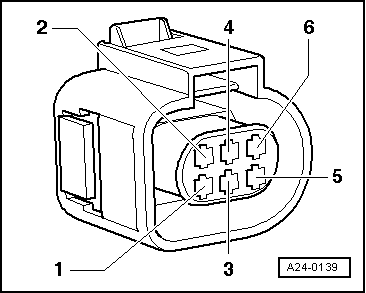
Checking the voltage supply to the throttle valve control part.

 
A24-0139
  • ‒ Unplug the connector from the throttle valve control part.
  • ‒ Switch the ignition on.
  • ‒ → Connect hand-held multimeter (voltage range) between the following contacts on the connector:

6-pin connector on the wiring harness, Contact.

Specification

2 + earth

approx. 5 V

2 + 6

approx. 5 V

If specifications are not attained, also check the signal and activation lines of the throttle valve actuator => Page 24-161.

If specifications are not attained:

Check wiring between engine control unit and throttle valve control part
=> Page 24-161.

Checking wiring

 
A24-0139
  • ‒ → Unplug the connector from the throttle valve control part.
  • ‒ Connect the V.A.G 1598/31 test box to wiring harness leading to engine control unit; the engine control unit should not be connected.
    => Page 24-23.

The following wiring connections are to be checked for open circuits and/or short to positive or negative.

6-pin connector on the wiring harness, Contact

Test box V.A.G 1598/31, Socket

1

92

2

83

3

117

4

84

5

118

6

91

  • ‒ Rectify any open/short circuit as necessary.

If no wiring fault is detected:

  • ‒ Replace throttle valve control part.

Checking accelerator position sender > < Performing adaption of throttle valve control part