audi Workshop Repair Guides

Audi Workshop Service and Repair Manuals

Testing injection quantity, leak tightness and spray pattern of injectors > < Checking fuel pressure regulator and holding pressure
Motronic Fuel Injection and Ignition System (6-cyl. Turbo)
Servicing Motronic injection system
Checking injectors
 
A96-0134

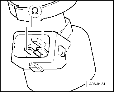
A - Electrical testing of injectors

  • ‒ Remove connector from the injector which is to be tested.
  • ‒ → Measure resistance between the valve contacts using V.A.G 1526.
  • Specification: 13.5...15.5 Ohm

When the engine is at operating temperature, the resistance is increased by approx. 4...6 ω.

  • ‒ If specification is not attained, replace injector .

B - Testing power supply

Test conditions

 
V96-0749
  • ● Fuse for injectors OK

=> Current Flow Diagrams, Electrical Fault-Finding and Fitting Locations

  • ‒ Remove connector from the injector which is to be tested.
  • ‒ → Connect diode test lamp V.A.G 1527 between contact 1 of the connector and engine earth.
  • ‒ Switch on ignition, the diode test lamp should come on.
  • ‒ If the diode test lamp does not light up, test for open circuits in the wiring between contact 1 and the fuse for the injectors - if necessary rectify open circuit.

=> Current Flow Diagrams, Electrical Fault-Finding and Fitting Locations

 
V96-0749
  • ‒ If the diode test lamp lights up, test activation of injectors.

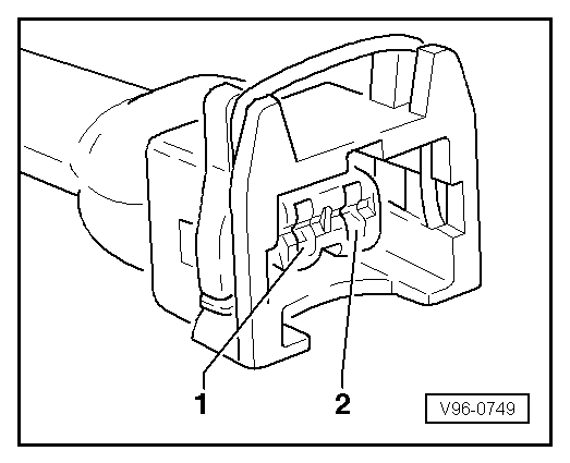
C - Testing activation of injectors

  • ‒ Remove connector from the injector which is to be tested.
  • ‒ → Connect diode test lamp V.A.G 1527 between contact 2 of connector and battery positive (+).
  • ‒ Operate starter for a few seconds (the engine can be allowed to start).

Specification: The diode test lamp should flash.

Note:

Diode test lamps with a low current draw continue to glow faintly between impulses from the engine control unit (rather than going out completely) and become much brighter when receiving an impulse.

 
V96-0749

If the diode test lamp does not flash:

  • ‒ Connect the V.A.G 1598/31 test box to wiring harness leading to engine control unit; the engine control unit should not be connected.
    => Page 24-23.
  • ‒ → Test wiring between contact 2 of respective injector connector and engine control unit for continuity or short to positive.

Contact 2 on plug connector of injector for cylinder

Test box V.A.G 1598/31, socket

1

96

2

112

3

88

4

97

5

113

6

89

  • ‒ Rectify any open/short circuit as necessary.
  • ‒ If the wiring is OK, replace engine control unit => Page 24-30.

Testing injection quantity, leak tightness and spray pattern of injectors > < Checking fuel pressure regulator and holding pressure