audi Workshop Repair Guides

Audi Workshop Service and Repair Manuals

Dismantling and assembling fuel manifold with injectors > < Checking injectors
Motronic Fuel Injection and Ignition System (6-cyl. Turbo)
Servicing Motronic injection system
Testing injection quantity, leak tightness and spray pattern of injectors

Test conditions

  • ● Fuel pressure OK, checking .

To gain access to the fuel rail (fuel manifold), the following steps must be performed. Procedure may vary depending on version.

 
A24-0150
  • ‒ → Release air duct at points indicated by arrows and remove air duct.

Some hoses must then be disconnected.

  • ‒ Be most careful about cleanliness.
  • ‒ After the test, renew the clamps/screw-type clips and secure them correctly.
 
A24-0151
  • Release solenoid valve for boost pressure limitation (N75) from fuel rail; hoses remain connected.
  • Disconnect connector on solenoid valve for activated charcoal filter (N80).
  • Disconnect connector on air recirculation valve for turbocharger (N249).
  • Open the clamps shown on the recirculation valve and pull off the hoses.
  • Open the clamps shown on the fuel pressure regulator and pull off the hoses.
  • Disconnect connectors from injectors, cylinder banks 1 and 2.
 
A24-0151
  • Open hose clamp and detach the hose (if required, vacuum is supplied to mechanical circulation valve via this hose).
  • Open the clamps shown and pull off the hoses. The hoses lead to the respective intakes of the bank 1 and bank 2 turbochargers.
  • Open hose clamp shown and detach the hose (fuel vapours are fed to the intake manifold via this hose).
 
A24-0151
  • Briefly open the screw connection on the fuel rail (supply line) in order to release pressure. Collect emerging fuel with a clean cloth. Retighten the screw connection.
  • Unscrew fuel rail from intake manifold (see arrows). (tightening torque of screws: 10 Nm).
  • ‒ Lift fuel rail and injectors from intake manifold and support.

Note:

  • ◆ After the fuel rail has been lifted, check whether the injectors are correctly fastened to it.
  • ◆ When fuel rail is lifted, individual injectors may become released and remain stuck in the intake manifold. In this case, the injectors should be refitted correctly to the fuel rail.
    .
 
A24-0137
  • ‒ → Connect the V.A.G 1598/31 test box to wiring harness leading to engine control unit; the engine control unit must not be connected.
    .
  • ‒ Place test box inside vehicle.

Leak test

  • ‒ Bridge contacts 1 and 65 on the test box using test leads from adapter set V.A.G 1594 (this creates an earth connection to one side of the fuel pump relay coil).

Note:

After bridging, the fuel pump runs continuously even if engine is not running; this is because the fuel pump relay is supplied with permanent positive via central electrics. The negative voltage supply for the fuel pump relay comes via the cable bridge in the test box.

  • ‒ Check injectors for leaks (visual check). When the fuel pump is running, only 1 or 2 drops a minute should escape from each injector.
 
A24-0069
  • ‒ If the fuel loss is greater, switch off fuel pump (remove cable bridge) and replace defective injector => Page 24-58.

Checking injection quantity

  • ‒ → Place injector to be tested in a measuring glass from injection quantity tester V.A.G 1602.
 
A24-0079
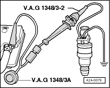
  • ‒ → Connect one of the injector contacts to engine earth using test cable and crocodile clamp from V.A.G 1594.
  • ‒ Connect second injector contact to positive using remote control V.A.G 1348/3 A, adapter cable V.A.G 1348/3-2 and auxiliary cable.

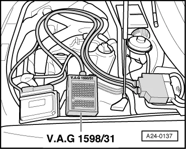
Ensure that test box is inside the vehicle.

  • ‒ Bridge contacts 1 and 65 on the test box using test leads from adapter set V.A.G 1594 (this creates an earth connection to one side of the fuel pump relay coil).

The fuel pump should run.

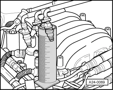
  • ‒ Activate the V.A.G 1348/3 A remote control for 30 seconds.
  • ‒ Once all three injectors of a cylinder bank have been actuated, place the three measuring glasses on a flat surface.
  • Specification per injector: 135...165 ml
  • ‒ If measured values for one or more injectors are outside tolerance, switch off fuel pump (switch off ignition) and replace defective injector => Page 24-58.
  • ‒ Repeat the check on injectors of second cylinder bank.
  • ‒ If the measured values for all the injectors are outside the tolerance range, check the fuel pressure => Page 24-40.

Note:

When checking the injection quantity, also check the spray pattern. The spray pattern should be the same for all the injectors.

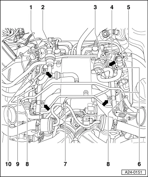
Notes on installation of fuel manifold and injectors:

Installation of the fuel manifold together with injectors is performed in the reverse sequence. The following points should be noted when installing:

  • ● Renew the O-rings at all opened connections. (when renewing the front O-ring, ensure that the plastic cap is not removed from the injector head. The O-ring must be pulled off over the plastic cap).
  • ● Moisten the O-rings with clean engine oil.
  • ● Insert injectors perpendicularly and in correct position into fuel manifold and secure with fasteners.
  • ● Position fuel rail with secured injectors on intake manifold and press evenly into place.
  • ● Renew hose clamps and ensure that they are securely fitted.

Dismantling and assembling fuel manifold with injectors > < Checking injectors