audi Workshop Repair Guides

Audi Workshop Service and Repair Manuals

Ignition system, glow plug system > < Check signal for rough-road recognition.
Motronic Fuel Injection and Ignition System (6-cylinder)
Checking auxiliary signals
Check data exchange between engine control unit and other CAN-control units

Notes:

  • ◆ Data is exchanged between individual control units by means of a bus system.
  • ◆ "CAN bus" is used to describe a system that transports and distributes data.
  • ◆ The wires between the control units that are used to transfer the data are known as signal wires.
  • ◆ Data is transmitted via data wires in sequence, i.e. in a specific order to the connected control units (e.g. engine rpm and accelerator pedal position).

Testing the bus system

The fault table includes instructions to test the data exchange between engine control units and CAN control units.and vehicle diagnostic, testing and information system VAS 5051 or fault reader V.A.G 1551 and select engine electronics control unit with "Address word" 01 .
For this purpose, the ignition must be switched on.

 
→ When adjacent display appears:
Rapid data transfer     HELP
Select function XX
  • ‒ Enter "08" to select the function "Reading measured value block" and confirm entry with Q key.
 
→ When adjacent display appears:
Reading measured value block    Q
Enter display group number XXX
  • ‒ Enter "125" for "display group number 125" and confirm entry with Q key.
  • ‒ Check displays in display zones 1 to 4.
  • Displayed engine control unit CAN-controlled control units:
    • ‒ No display: Control not CAN-controlled
    • ‒ Display 1: CAN-controlled control unit is user of the Databus
    • ‒ Display 0: CAN-controlled control unit is not user of the Databus

Note:

The measured value blocks 125 and 126 indicate CAN drive users.

  • ‒ Press the ⇒key.
 
→ When indicated on display:
Rapid data transfer     HELP
Select function XX
  • ‒ Enter "06" for "End output" function and confirm entry with Q key.
 
→ When indicated on display:
Rapid data transfer     HELP
Enter address word XX
  • ‒ Press the "0" key twice for the address word "automatic test sequence" and confirm entry with Q key.
    • ‒ The fault memory interrogation of all vehicle systems capable of self-diagnosis is carried out

If a control unit answers with its identification, the number of faults stored or "No fault detected" appears on the display.

Any system faults stored will be displayed in sequence and printed out. The V.A.G 1551 will then transmit the next address word.

 
→ The automatic test sequence has ended when the following appears on the display:
V.A.G - SELF DIAGNOSIS    HELP
1 - Rapid data transfer*
2 - Flash code output*

If a fault is displayed relating to "Databus... " or "...CAN bus":

  • ‒ Check whether this is the correct engine control unit for this vehicle and if further CAN control unit are installed (part no. and coding).

If the correct control units are installed:

  • ‒ Check that multiple connectors for control units are properly seated.

If the multiple connectors are too tight:

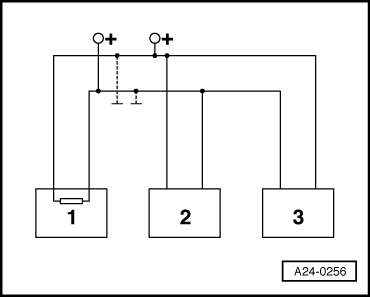
  • ‒ Check the CAN bus system.

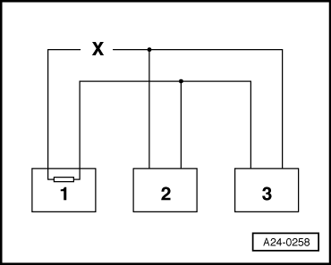
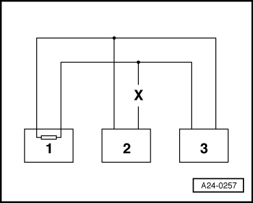
Checking a "two-line bus system"

The communication between three or more control units is carried out over a "two-line bus system".

  • ‒ Evaluate the faults stored in the control units.

Note:

This helps to localise line faults.

Example 1:

With the faults stored in the fault memories it can be seen that the control unit 1 does not communicate with control units 2 and 3.

 
A24-0258

Control unit

Faults stored in fault memory

1

- No message from control unit 2
- No message from control unit 3

2

- No message from control unit 1

3

- No message from control unit 1

  • ‒ Switch ignition off.
  • ‒ Disconnect the control units connected to each other via the bus lines and investigate whether there is an open circuit between the bus lines.

=> Current Flow Diagrams, Electrical Fault-Finding and Fitting Locations

  • ‒ If no fault can be detected in the bus lines exchange control unit 1.

Example 2:

With the faults stored in the fault memories it can be seen that the control unit 2 does not communicate with control units 1 and 3.

 
A24-0257

Control unit

Faults stored in fault memory

1

- No message from control unit 2

2

- No message from control unit 1
- No message from control unit 3

3

- No message from control unit 2

  • ‒ Switch ignition off.
  • ‒ Disconnect the control units connected to each other via the bus lines and investigate whether there is an open circuit between the bus lines.

=> Current Flow Diagrams, Electrical Fault-Finding and Fitting Locations

  • ‒ If no fault can be detected in the bus lines exchange control unit 2.

Example 3:

With the faults stored in the fault memories it can be seen that there is no sending or receiving operation possible in any of the control units.

Control unit

Faults stored in fault memory

1

- Data bus drive defective

2

- Data bus drive defective

3

- Data bus drive defective

  • ‒ Switch ignition off.
 
A24-0256
  • ‒ → Disconnect the control units that are linked by the bus wires and check for a short circuit to positive or mass between the bus wires.

=> Current Flow Diagrams, Electrical Fault-Finding and Fitting Locations

If cause of fault "Data bus drive defective" cannot be found in bus lines check whether one of the control units is responsible for the fault.

All the control units that communicate via the CAN data bus are still disconnected. Ignition is switched off.

  • ‒ Connect one of the control units.
  • ‒ Connect fault reader V.A.G 1551. Switch the ignition on and erase the fault memory of the control unit that has just been connected Terminate fault readout by selecting function 06 "End output".
  • ‒ Switch the ignition off and then on again.
  • ‒ Leave the ignition switched on for 10 seconds. Then interrogate the fault memory of the control unit that has just been connected, using the fault reader.
  • ‒ If the fault "Data bus drive defective" is now indicated, replace the control unit which has just been connected.
  • ‒ If fault "Signal wire defect" is not read out, connect the next control unit and repeat the procedure.

Ignition system, glow plug system > < Check signal for rough-road recognition.