
A4 Mk1
|
Checking lambda control
Checking lambda probe and lambda control upstream of catalytic converter
|
| → When indicated on display: |
|
||
Note: During basic setting, the solenoid valve for the active carbon canister (valve -N80) is closed and the air conditioner compressor is switched off. |
| → When indicated on display: |
|
||
|
| → When adjacent display appears: |
|
||
|
| → When adjacent display appears: |
|
|||||||||||||||||||||||||||||||||||||||||||||||||||||||
Interpreting display group 033
| ||||||||||||||||||||||||||||||||||||||||||||||||||||||||
| → When indicated on display: |
|
|||||||||||||||||||||||||||||||||||||||||||||||||||||||||||||||||||||||||||||||||||||||||
Interpreting display group 032
Interpreting display group 032
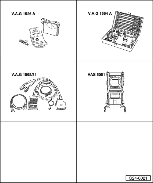
Checking basic voltage Fitting location of connectors => Installation position overview Page 24-5 Test requirements:
=> Current Flow Diagrams, Electrical Fault-Finding and Fitting Locations
| ||||||||||||||||||||||||||||||||||||||||||||||||||||||||||||||||||||||||||||||||||||||||||
 |
|
If specified value is not attained:
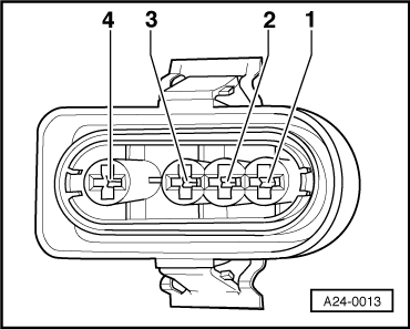
Check lambda probe wiring Bank 1 lambda probe 1 upstream of catalytic converter -G39 Fitting location of connectors => Installation position overview Page 24-5
|
|
||||||||||
|
|
|||||||
If no wiring fault is detected:
Checking lambda probe wiring bank 2 lambda probe 1 upstream of catalytic converter -G108 Fitting location of connectors => Installation position overview Page 24-5
|
|
||||||||||||||||
If no wiring fault is detected:
|