audi Workshop Repair Guides

Audi Workshop Service and Repair Manuals

Checking fuel tank breather > < Checking secondary air inlet valve -N112
Motronic fuel injection and ignition system (6 cyl.)
Checking secondary air system
Checking secondary air pump relay -J299 and actuation
 
G24-0022

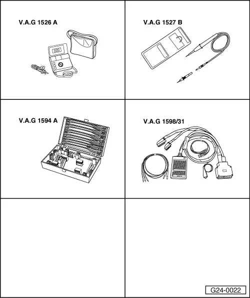
Special tools, testers and workshop equipment required

  • ◆ V.A.G 1526 A
  • ◆ V.A.G 1527 B
  • ◆ V.A.G 1594 A
  • ◆ V.A.G 1598/31

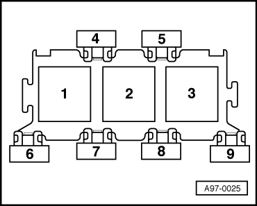
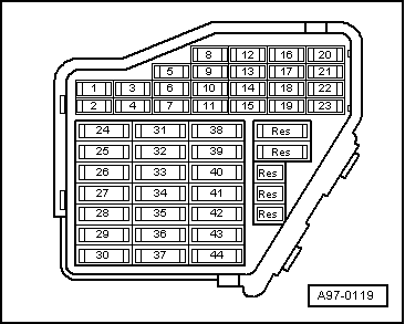
Installation position => Overview installation positions - Page 24-5

Test sequence

  • ‒ Start the final control diagnosis and activate secondary air pump relay -J299
    .
 
A97-0025
    • ‒ → Secondary air pump relay (in 3-position relay carrier in plenum chamber electronics box on left, position 2) must be energised and secondary air pump motor -V101 must run in intervals.

A - If relay is not energised:

  • ‒ Check voltage supply of secondary air pump relay => Page 24-113.
  • ‒ Check actuation of secondary air pump relay => Page 24-115.

B - If relay is energised but secondary air pump motor does not run:

  • ‒ Check voltage supply of secondary air pump motor => Page 24-116.

Check voltage supply of secondary air pump relay

  • ‒ Switch off ignition.
  • ‒ Pull off secondary air pump relay.
  • ‒ Connect up multimeter as follows to measure voltage.

3-position relay carrier in E-box in plenum chamber, position 2
Contact

Measure to

8

Engine earth

    • ‒ Specified value: approx. battery voltage

If the specified value is not attained:

 
A97-0025
  • ‒ Carry out the following tests (marked with dots):
  • ● → Check fuse S130 (40 A) in 3-position relay carrier in E-box of plenum chamber, position 7
  • ● Check for open circuit in wiring from battery-+ (terminal 30) to fuse S130 for secondary air pump relay -J299 (in 3-position in E-box of plenum chamber , position 2).

=> "Current Flow Diagrams, Electrical Fault Finding and Installation locations" binder

  • ‒ Connect up multimeter as follows to measure voltage.

3-position relay carrier in E-box in plenum chamber, position 2
Contact

Measure to

4

Engine earth

  • ‒ Operate starter briefly.
    • ‒ Specified value: approx. battery voltage

If the specified value is not attained:

  • ‒ Carry out the following tests (marked with dots):
 
A97-0119
  • ● → Check fuse S234 (in fuse holder, position 34).
  • ● Check for open circuit in wiring from secondary air pump relay -J299 (in 3-position relay carrier in E-box of plenum chamber) via fuse S234 (in fuse box, position 34) to fuel pump relay.

=> "Current Flow Diagrams, Electrical Fault Finding and Installation locations" binder

Check actuation of secondary air pump relay

  • ‒ Switch off ignition.
  • ‒ Pull off secondary air pump relay.
  • ‒ Connect voltage tester V.A.G 1527 B as follows:

3-position relay carrier in E-box in plenum chamber, position 2
contact

Measure to

6

Battery positive

  • ‒ Start the final control diagnosis and activate secondary air pump relay -J299
    => Page 01-37.
    • ‒ The LED should flash.

If LED does not flash:

  • ‒ Switch off ignition.
  • ‒ Connect the V.A.G 1598/31 test box to wiring harness leading to engine control unit; engine control unit should not be connected => Page 24-20.
  • ‒ Check for open circuit and short to positive or earth in the following wiring connections:

3-position relay carrier in E-box in plenum chamber, position 2
Contact

Test box V.A.G 1598/31
Bush

6

46

  • ‒ Rectify any open/short as necessary.

If no fault is found:

  • ‒ Replace secondary air pump relay
    -J299.

Check voltage supply for secondary air pump motor

  • ‒ Pull plug off secondary air pump motor -V101.
  • ‒ Connect up voltage tester V.A.G 1527 B between contacts 1 and 2.
  • ‒ Start the final control diagnosis and activate secondary air pump relay -J299
    => Page 01-37.
    • ‒ The LED should flash.

If LED does not flash:

  • ‒ Carry out the following tests (marked with dots):
  • ● Check for open circuit in wiring from plug at motor -V101 to secondary air pump relay -J299 (in 3-position relay carrier in E-box of plenum chamber, position 2).

=> "Current Flow Diagrams, Electrical Fault Finding and Installation locations" binder

  • ● Check for open circuit in wiring between plug at motor -V101 and earth connection 1 in engine compartment wiring harness.

=> "Current Flow Diagrams, Electrical Fault Finding and Installation locations" binder

If no fault is found:

  • ‒ Replace secondary air pump motor
    -V101.

Checking fuel tank breather > < Checking secondary air inlet valve -N112