audi Workshop Repair Guides

Audi Workshop Service and Repair Manuals

Removing and installing injection system components > < Technical data
Motronic fuel injection and ignition system (6 cyl.)
Servicing Motronic injection system
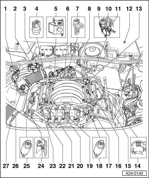
Installation locations overview
 
A24-0140

Note:

Further installation locations

=> Fig.24-9

up to Fig.24-10.

  • Solenoid valve 1 for activated charcoal filter -N80
  • 4-pin connector
    • ◆ for Lambda probe 1 -G39
  • 3-pin connector
    • ◆ For knock sensor 1 -G61
    • ◆ Brown
  • Coolant temperature sender -G62
    • ◆ On coolant pipe behind cylinder head, bank 1
 
A24-0140
  • Secondary air inlet valve -N112
    • ◆ Only on vehicles with secondary air induction
  • Throttle valve control unit -J338
  • Intake air temperature sender -G42
  • Intake manifold changeover valve -N156
  • 4-pin connector
    • ◆ for Lambda probe 2 -G108 and Lambda probe heating -Z28
  • 3-pin connector
    • ◆ For engine speed sender -G28
    • ◆ Grey
  • 3-pin connector
    • ◆ For knock sensor 2 -G66
    • ◆ Brown
 
A24-0140
  • In E-box in plenum chamber
    • ◆ Engine control unit -J220
    • ◆ Secondary air pump relay -J299 (only on vehicles with secondary air induction)
      => Fig.24-10
  • Fuel pressure regulator
  • Hall sender -G40
    • ◆ Cylinder bank 2
  • Lambda probe 2 -G108
  • Engine speed sender -G28
    • ◆ In gear case above ring gear
  • Knock sensor 2 -G66
  • Camshaft adjustment solenoid valve 2 -N208
 
A24-0140
  • Ignition coils -N, -N128, -N158
    • ◆ With output stage -N122
  • Knock sensor 1 -G61
  • Injectors -N30...-N33
    -N83, -N84
  • Hall sender -G163
    • ◆ Cylinder bank 1
  • Lambda probe 1 -G39
  • Earth connection
    • ◆ On right hand engine support
  • Camshaft adjustment solenoid valve 1 -N205
  • Air mass meter -G70
  • Secondary air pump motor
    -V101
 
A24-0143

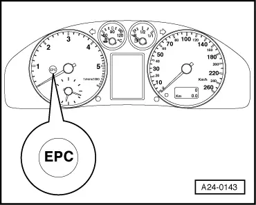
→ Fig.1    Installation position warning lamp for electronic throttle control -K132

 
A24-0204

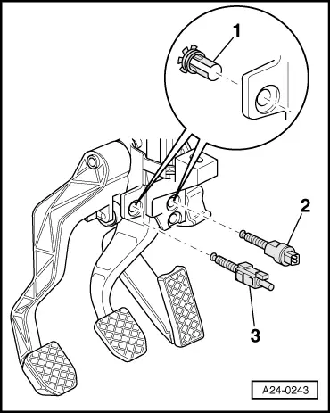
→ Fig.2    Installation position for gas pedal position sender -G79 and sender 2 for gas pedal position -G185

 
A24-0243

→ Fig.3    Installation position brake light switch -F and brake pedal switch -F47, clutch pedal switch -F36

  •     1 -    Clip
  •     2 -    Brake light switch -F, brake pedal switch -F47
  •     3 -     Clutch pedal switch -F36

Note:

Switch must only be installed once in order to ensure that it is sufficiently tight.

Adjust switch:

  • ‒ Insert switch -2- or -3- into mounted clip-1- and press in as far as possible.
  • ‒ Pull the brake or clutch pedal back as far as it will go. This adjusts the switch.
 
N01-0111

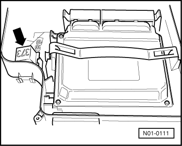
→ Fig.4    Installation position secondary air inlet valve relay -J299

Relay for secondary air inlet valve -J299 -arrow-.

Removing and installing injection system components > < Technical data