audi Workshop Repair Guides

Audi Workshop Service and Repair Manuals

Testing intake air temperature sender -G42 > < Testing output stage -N122 for ignition coils
Motronic injection and ignition system (4-cyl. turbo)
Testing ignition system
Testing Motronic current supply relay -J271 - Vehicles from model year 2000 onwards
 
G24-0020

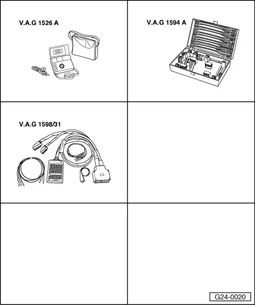
Special tools and workshop equipment required

  • ◆ V.A.G 1526 A
  • ◆ V.A.G 1594 A
  • ◆ V.A.G 1598/31
 
A97-0119

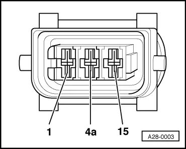
Note:

The Motronic current supply relay -J271 supplies voltage to the ignition coils with output stages and to the engine control unit (pin 121).

Test requirement:

  • ● Fuse No. 229 OK (in fuse box, socket position 29)

 
A28-0003

Test sequence

  • ‒ → Unplug 3-pin connector from one ignition coil.
  • ‒ Connect multimeter (voltage measurement range) as follows:

Connector
Contact

Measure against

15

Engine earth

  • ‒ Switch on ignition.
    • ‒ Specification: approx. battery voltage
 
A20-0564
  • ‒ → Remove rubber seal from plenum chamber in direction of arrow-.
  • ‒ Remove plenum chamber cover -1- from the front.

 
A10-0761
  • ‒ → Remove cover for electronics box in plenum chamber -arrows-.
 
A26-0357
  • ‒ → Unplug current supply relay -3-.

 
A24-0298
  • ‒ → Test for open circuits in the following wiring connection according to current flow diagram:

3-way relay carrier in electronics box in plenum chamber (plug-in position 3)
Contact

Connectors on ignition coils

Contact

6

15

  • ‒ Rectify any open circuit as necessary.

If the wiring is OK:

  • ‒ Test supply voltage for Motronic current supply relay -J271 .
  • ‒ Test activation of Motronic current supply relay -J271 => Page 28-25.
 
A24-0298

Checking voltage supply

  • ‒ → Connect multimeter (voltage measurement range) as follows:

3-way relay carrier in electronics box in plenum chamber (plug-in position 3)
Contact

Measure against

2

Engine earth

9

Engine earth

    • ‒ Specification: approx. battery voltage

If the specification is not attained:

  • ‒ Check for open circuit in wiring between central electrics unit and current supply relay.

=> Current flow diagrams, Electrical fault finding and Fitting locations binder

 
A24-0298

If no fault is detected in the wiring:

Checking activation

  • ‒ → Connect multimeter (voltage measurement range) as follows:

3-way relay carrier in electronics box in plenum chamber (plug-in position 3)
Contact

Measure against

4

Battery positive

  • ‒ Switch on ignition.
    • ‒ Specification: approx. battery voltage

If the specification is not attained:

  • ‒ Switch off ignition.
  • ‒ Connect test box V.A.G 1598/31 to wiring harness for engine control unit. Do not connect to the engine control unit itself.
    => Page 24-20.
 
A24-0298
  • ‒ → Test for open circuit and short to positive or earth in the following wiring connections:

3-way relay carrier in electronics box in plenum chamber (plug-in position 3)
Contact

Test box V.A.G 1598/31
Socket

4

21

  • ‒ Rectify any open/short circuit as necessary.

If no fault is found:

  • ‒ Fit a new Motronic current supply relay -J271.

Testing intake air temperature sender -G42 > < Testing output stage -N122 for ignition coils