audi Workshop Repair Guides

Audi Workshop Service and Repair Manuals

Testing knock sensor control limit > < Checking control unit voltage supply
Motronic injection and ignition system (4-cyl.)
Testing ignition system
Testing engine speed sender -G28

Notes:

  • ◆ The engine speed sender is a combined speed sender and reference mark sender.
  • ◆ Without a signal from engine speed sender -G28 the engine cannot be started.
  • ◆ If the signal from engine speed sender -G28 fails while the engine is running, the engine will cut out immediately.

Testing engine speed sender

Fitting location of sender and connector
.

 
A28-0029
  • ‒ Before carrying out the test, make sure that the sender is correctly installed and firmly seated.
  • ‒ Check for damage or metal particles on sender and sender wheel.
  • ‒ Unplug connector for engine speed sender (grey connector).
  • ‒ → Connect hand-held multimeter V.A.G 1526 A (resistance test range) to contacts 1 and 2 on connector in connector support bracket using test lead from V.A.G 1594.
  • Specification: approx. 450...1000 ω

Notes:

  • ◆ The resistance value for the engine speed sender is based on a temperature of 20 °C.
  • ◆ The resistance increases as the temperature rises.

If the specification is not attained:

 
A28-0029
  • ‒ Fit a new engine speed sender.

If the specification is attained:

  • ‒ → Connect hand-held multimeter V.A.G 1526 (resistance test range) between contacts 2 and 3 (earth) and between contacts 1 and 3 (earth).
  • Specification: ∞ω (infinity / open circuit) in each test

If the specification is not attained:

  • ‒ Fit a new engine speed sender.

If the specification is attained:

  • ‒ Test the wiring between the sender connector and the engine control unit as follows:
  • ‒ Connect test box V.A.G 1598/31 to wiring harness for engine control unit. Do not connect to the engine control unit itself.
    => Page 24-10.
 
V96-0836
  • ‒ → Test wiring connection from 3-pin connector (sender connector) ...
  • ‒ ... to engine control unit for open circuit and/or short circuit to positive or earth.

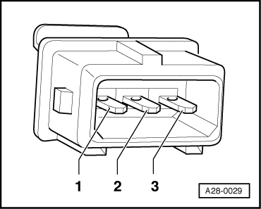
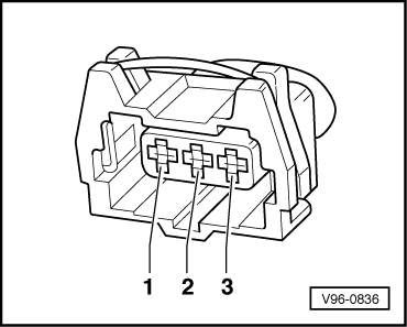
3-pin connector on wiring harness, socket

Test box V.A.G 1598/31, socket

1 (signal wire)

82

2 (earth wire)

90

3 (screening)

108

  • Resistance in wiring: max. 1.5 ω

=> Current flow diagrams, Electrical fault finding and Fitting locations binder

  • ‒ Rectify any open/short circuit as necessary.

If no fault is found in the wiring:

  • ‒ Slowly rotate the engine and check that sender wheel has no run-out and is securely mounted.
  • ‒ If no faults have been found in any of the tests so far, fit a new engine control unit .

Testing knock sensor control limit > < Checking control unit voltage supply