audi Workshop Repair Guides

Audi Workshop Service and Repair Manuals

Testing camshaft timing control > < Testing knock sensors -G61 and -G66
Motronic injection and ignition system (4-cyl.)
Testing ignition system
Testing Hall sender -G40

The Hall sender indicates the ignition position for Cylinder 1.

If the Hall sender fails to function, the knock control is switched off and the ignition timing is retarded slightly because the signals can no longer be assigned to the cylinders.

Even without a signal from the Hall sender the engine will continue to run and can also be re-started.

  • ◆ When a fault is detected the engine control unit produces one spark per crankshaft revolution for each cylinder.
  • ◆ The fact that the injection system is one revolution out of phase does not have any noticeable effect on the fuel injection. If this happens, the fuel is injected upstream of the closed inlet valve instead of while the inlet valve is open. This has only a minor influence on the quality of the air/fuel mixture.
 
A24-0213

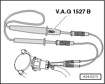
Testing activation of Hall sender

Use test leads from adapter set V.A.G 1594 when carrying out the following tests.

Fitting location of Hall sender -G40 .

  • ‒ Push back rubber sleeve on Hall sender connector.
  • ‒ → Connect diode test lamp V.A.G 1527 to contacts 1 and 2 of the Hall sender connector from behind (without unplugging the connector from the Hall sender).

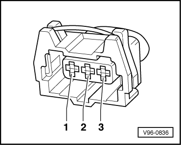
Note:

The connector contacts are numbered on the back of the connector.

  • ‒ Operate starter for a few seconds.

The diode test lamp should flash briefly once every two engine revolutions.

Note:

Diode test lamps with a low current draw continue to glow faintly between impulses from the engine control unit (rather than going out completely) and become much brighter when receiving an impulse.

If the diode test lamp does not flash, test the voltage supply.

Test voltage supply for Hall sender:

  • ‒ Unplug connector from Hall sender.
  • ‒ Switch ignition on.
 
V96-0836
  • ‒ → Connect hand-held multimeter V.A.G 1526 (voltage measurement range) between engine earth and socket 1 of connector.
  • Specification: approx. 5 V

Testing signal wire for Hall sender:

  • ‒ Switch ignition on.
  • ‒ → Connect hand-held multimeter V.A.G 1526 (voltage measurement range) between engine earth and socket 2 of relevant connector.
  • Specification: approx. battery voltage

Testing earth connection for Hall sender:

 
V96-0836
  • ‒ → Connect hand-held multimeter V.A.G 1526 (resistance measurement range) between socket 3 on connector and engine earth.
  • Specification: Continuity
  • Resistance in wiring: max. 1.5 ω

If all the readouts match the specifications but the diode test lamp does not flash (measurement taken between socket 1 and 2 without unplugging connector and while operating starter):

  • ‒ Renew Hall sender.

If the readouts do not match the specification, test the wiring.

Testing wiring between Hall sender and engine control unit

  • ‒ Connect test box V.A.G 1598/31 to wiring harness for engine control unit. Do not connect to the engine control unit itself.
    .
 
V96-0836
  • ‒ → Test wiring connection from Hall sender ....
  • ‒ .... to engine control unit for open circuit and/or short circuit to positive or earth.

3-pin connector on
wiring harness, socket

Test box V.A.G 1598/31, socket

1 (positive)

98

2 (signal)

86

3 (earth)

108

  • Resistance in wiring: max. 1.5 ω

=> Current flow diagrams, Electrical fault finding and Fitting locations binder

  • ‒ Rectify any open/short circuit as necessary.
  • ‒ If all the test results so far have been OK but a fault related to the camshaft sensor (Hall sender) is displayed again after erasing the fault memory as a test measure, the cause may be as follows:
    • ‒ Rotor ring for Hall sender misaligned; test phase position => Page 28-24.

Testing phase position of Hall sender

  • ‒ Connect vehicle diagnostic, testing and information system VAS 5051 (or fault reader V.A.G 1551) and select engine electronics control unit by entering address word "01" ( => Page 01-3.)
    When doing this the engine must be idling.
 
→ Indicated on display:
Rapid data transfer    HELP
Select function XX
  • ‒ Press keys 0 and 8 for the function "Read measured value block" and confirm entry with Q key.
 
→ Indicated on display:
Read measured value block    
Enter display group number XXX
  • ‒ Press keys 0, 9 and 3 to select Display Group 93 and confirm entry with Q key.
 
→ Indicated on display:
Read measured value block 93    ⇒
    1    2    3    4
  • ‒ Check display values for Hall senders.

Display zones

1

2

3

4

Display Group 93: Phase position of Hall sender with engine idling

Display

xxx rpm

xx %

0 ± 7 ° crankshaft

Indicates

Engine speed

Engine load

Phase position
Bank 1

Range

min.: 750 rpm
max.: 6800 rpm


min.: -20.3 ° crankshaft
max.: 14.8 ° crankshaft

Specification

810...910 rpm

0 ± 7 °
crankshaft

Note

If readouts do not match specifications, unbolt Hall sender and check whether rotor ring is properly mounted on camshaft. If it is wrongly mounted, the locating lug will be flattened when the securing bolt is tightened. Also check valve timing.

Testing camshaft timing control > < Testing knock sensors -G61 and -G66