
A4 Mk1
 |
|
|
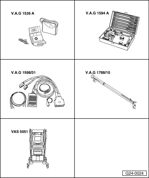
Special tools and workshop equipment required
Requirements for test:
Test sequence
Test requirement:
|
| → Indicated on display: |
|
||
|
| → Indicated on display: |
|
|||||||||||||||||||||||||||||||||||||||||||||||||||||||||||||||||
Note: The "lambda probe status" display indicates the status of the lambda control and lambda probes.
Notes:
Testing lambda control (after catalytic converter) Test requirement:
| ||||||||||||||||||||||||||||||||||||||||||||||||||||||||||||||||||
| → Indicated on display: |
|
||
|
| → Indicated on display: |
|
|||||||||||||||||||||||||||||||||||||||||||||||||||||||
Note on display zone 2: The lambda probe voltage (Bank 1, Probe 2) should remain more or less constant. Large voltage fluctuations indicate that the catalytic converter is damaged. Reading Display Group 037
Further notes If the readout in display zone 3 or 4 does not match the specification:
If the readout in display zone 3 or 4 still does not match the specification even after the test drive:
Note: If the lambda probe voltage is OK and the compensating value is still above 0.02 even after a test drive, this points to excessive ageing of the lambda probe before catalytic converter. Testing basic voltage | ||||||||||||||||||||||||||||||||||||||||||||||||||||||||
 |
|
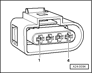
Note: For access to connector, unscrew bolts securing coolant expansion tank and pivot expansion tank clear to the side. The coolant hoses do not have to be disconnected. |
|
|
Note: For access to connector, unscrew bolts securing coolant expansion tank and pivot expansion tank clear to the side. The coolant hoses do not have to be disconnected.
|
 |
|||||||
=> Current flow diagrams, Electrical fault finding and Fitting locations binder
If the wiring is OK:
|