audi Workshop Repair Guides

Audi Workshop Service and Repair Manuals

Testing lambda probe signal wiring and activation > < Testing lambda probe and lambda control
Motronic injection and ignition system (4-cyl.)
Testing lambda control (engine codes:APT, ARG)
Checking Lambda probe heating

Note:

The lambda probe heating circuit is monitored by the self-diagnosis system.

 
A24-0088
  • ‒ Interrogate fault memory .
  • ‒ Unplug 4-pin connector for lambda probe -G39.
  • ‒ → Connect hand-held multimeter (resistance measurement range) between contacts 1 and 2 of the lambda probe connector using test leads from V.A.G 1594.
  • ‒ Measure the resistance.
  • Specification at room temperature: 2...15 ω

Note:

The resistance of the heating element at room temperature is approx. 1...5 ω. With even a small temperature rise this value will increase sharply.

If the specification is not attained:

  • ‒ Renew the lambda probe.

If the specification is obtained:

  • ‒ Test voltage supply for lambda probe heating

Testing voltage supply for lambda probe heating

  • ‒ Test fuse for lambda probe heating

=> Current flow diagrams, Electrical fault finding and Fitting locations binder

 
A24-0094

If the fuse is OK:

  • ‒ → Connect hand-held multimeter (voltage measurement range) between sockets 1 (positive) and 2 (earth) using test leads from V.A.G 1594.
  • ‒ Operate the starter briefly.
  • Specification: approx. battery voltage

If there is no voltage reading:

 
A24-0094
  • ‒ → Connect hand-held multimeter (voltage measurement range) between socket 1 (positive) and vehicle earth using test leads from V.A.G 1594.
  • ‒ Operate the starter briefly.
  • Specification: approx. battery voltage

If there is still no voltage reading:

  • ‒ Test for open circuit and/or short circuit in wiring between fuel pump relay and socket 1 on the lambda probe connector (on wiring harness) via fuse.

=> Current flow diagrams, Electrical fault finding and Fitting locations binder

If the voltage supply is OK:

 
A24-0094
  • ‒ → Connect hand-held multimeter (voltage measurement range) between socket 2 (switched earth connection from engine control unit) and battery positive terminal using test leads from V.A.G 1594.
  • ‒ Start the engine.
  • Specification: approx. battery voltage (fluctuating)

Note:

At certain points in the operating range the engine control unit continuously "switches" the earth connection to the lambda probe heating. In other words, it repeatedly makes and breaks the earth connection at these points. For this reason the voltage reading on the tester may fluctuate.

  • ‒ Switch off ignition.

If there is no voltage reading:

 
A24-0094
  • ‒ Connect test box V.A.G 1598/31 to wiring harness for engine control unit. Do not connect to the engine control unit itself.
    => Page 24-10.
  • ‒ → Test for open circuits in the following wiring connection:

Connector
Socket

Test box V.A.G 1598/31
Socket

2

5

  • ‒ Rectify any open circuits.

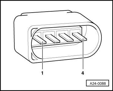
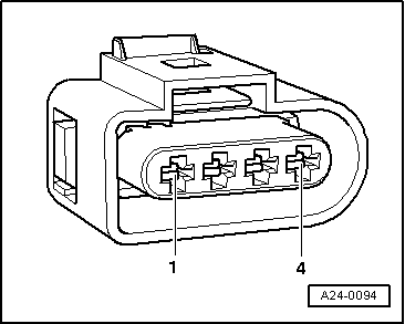
If the wiring is OK but the lambda probe heating still has no earth connection:

  • ‒ Fit a new engine control unit => Page 24-13.

Testing lambda probe signal wiring and activation > < Testing lambda probe and lambda control