audi Workshop Repair Guides

Audi Workshop Service and Repair Manuals

Testing voltage supply for control unit > < Testing engine speed sender -G28
Motronic injection and ignition system (4-cyl. turbo)
Testing ignition system
Testing coolant temperature sender -G62
 
G24-0021

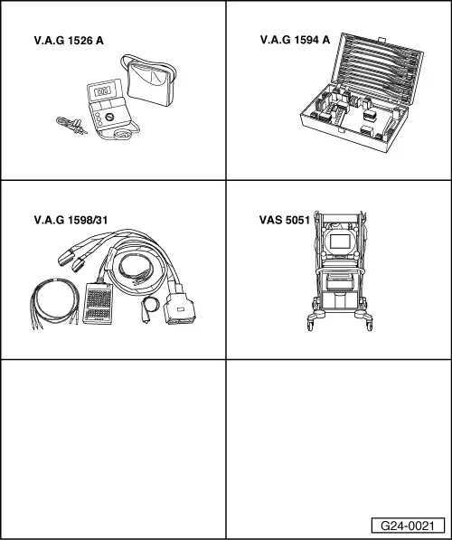
Special tools and workshop equipment required

  • ◆ V.A.G 1526 A
  • ◆ V.A.G 1594 A
  • ◆ V.A.G 1598/31
  • ◆ VAS 5051 with VAS 5051/1

or

  • ◆ V.A.G 1551 with V.A.G 1551/3 A

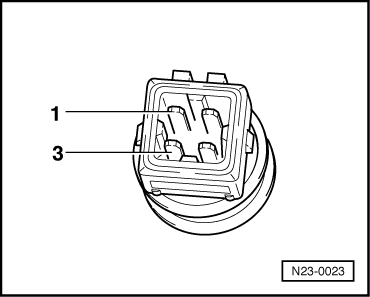
Fitting location => Fitting locations overview, Page 24-5

Test requirement:

  • ● Engine cold

Test sequence

  • ‒ Connect vehicle diagnostic, testing and information system VAS 5051 (or fault reader V.A.G 1551). Select engine electronics control unit by entering the address word "01" ; when doing this the engine must be running at idling speed.
 
→ Indicated on display:
Rapid data transfer     HELP
Select function XX
  • ‒ Enter "08" to select the function "Read measured value block" and confirm entry with Q key.
 
→ Indicated on display:
Read measured value block    Q
Enter display group number XXX
  • ‒ Enter "004" to select Display Group 004 and confirm entry with Q key.
 
→ Indicated on display:
Read measured value block 4    ⇒
    1    2    3    4
  • ‒ Check display in display zone 3.

Display zones

1

2

3

4

Display Group 004: Coolant temperature with engine idling

Display

xxxx rpm

xx.x V

xxx.x °C

xxx.x °C

Indicates

Engine speed

Battery voltage

Coolant temperature

Intake air temperature

Range

0 ... 6800 rpm

10.0 ... 15.0 V

-48.0 ... 143.0 °C

-48.0 ... 143.0 °C

Specification

xxxx rpm

12.0 ...15.0 V

Temperature display should rise steadily

Between ambient temperature and 110 °C

 
N23-0023

If display zone 3 shows an implausible value:

  • ‒ Unplug connector on coolant temperature sender.
  • ‒ → Connect multimeter (resistance measurement range) between contacts 1 and 3 on the sender.

 
N24-0157

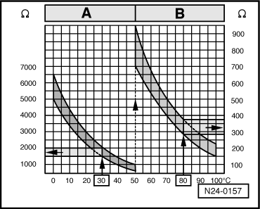
Scale A shows resistance values for temperature range 0...50 °C and scale B the values for temperature range 50...100 °C.

→ Examples:

  • ◆ 30 °C corresponds to a resistance from 1500...2000 ω
  • ◆ 80 °C corresponds to a resistance from 275...375 ω

If the specification is not attained:

  • ‒ Fit a new coolant temperature sender.
 
N23-0020

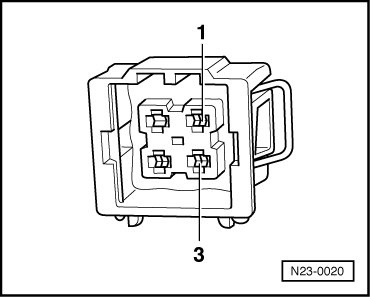
If the specification is obtained:

  • ‒ Connect test box V.A.G 1598/31 to wiring harness for engine control unit. Do not connect to the engine control unit itself.
    => Page 24-20.
  • ‒ → Test for open circuit and short to positive or earth in the following wiring connections:

Connector
Contact

Test box V.A.G 1598/31
Socket

1 (signal)

93

3

108

  • ‒ Test for short circuits between the two wires.
  • ‒ Rectify any open/short circuit as necessary.

If no fault is detected in the wiring:

  • ‒ Fit a new engine control unit => Page 24-24.

Testing voltage supply for control unit > < Testing engine speed sender -G28