audi Workshop Repair Guides

Audi Workshop Service and Repair Manuals

Testing output stage -N122 for ignition coils > < Removing and installing parts of the ignition system
Motronic injection and ignition system (4-cyl. turbo)
Testing ignition system
Testing ignition coils
 
G24-0022

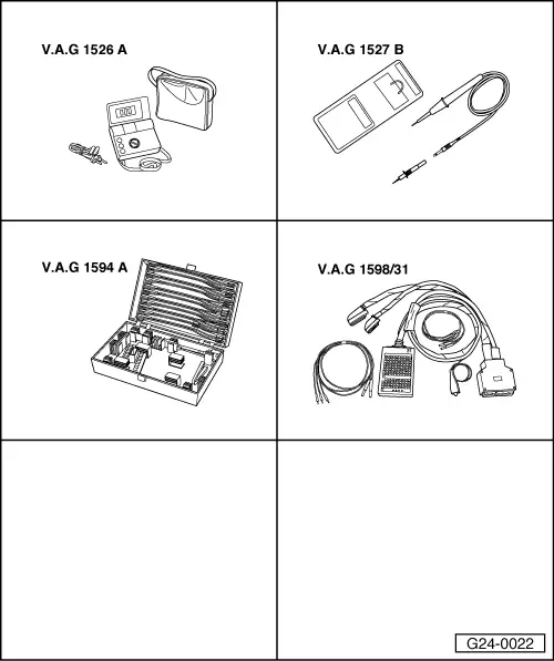
Special tools and workshop equipment required

  • ◆ V.A.G 1526 A
  • ◆ V.A.G 1527 B
  • ◆ V.A.G 1594 A
  • ◆ V.A.G 1598/31
 
A10-0661

Test sequence

The procedure for identifying an inoperative or misfiring cylinder is as follows:

  • ‒ → Remove engine cover panel -arrows-.
  • ‒ Unplug the connectors from the injectors in turn with the engine running, and observe how the engine runs.
  • or
  • ‒ Compare the spark plugs of all cylinders with each other and check for soot on the electrodes.

When the defective cylinder has been identified:

  • ‒ Connect hand-held multimeter (resistance measurement range) to spark plug connector.
    • ‒ Specification: approx. 2 kω

If the specification is not obtained:

  • ‒ Renew spark plug connector.

If the specification is obtained:

  • ‒ Swap spark plug of defective cylinder with one from another cylinder.

If the fault moves with the spark plug:

  • ‒ Renew spark plug.

If the fault remains in the same cylinder:

  • ‒ Swap ignition coil of defective cylinder with one from another cylinder.

If the fault moves with the ignition coil:

  • ‒ Renew ignition coil.

If the fault remains in the same cylinder:

 
A28-0003

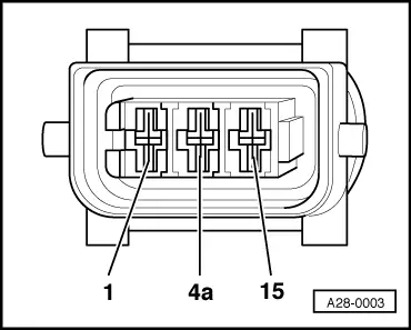
Test earth connection for ignition coil:

  • ‒ Unplug connector from ignition coil.
  • ‒ → Test earth connection from contact 4a on the 3-pin connector to engine earth for open circuit or short circuit to positive.
  • ‒ Rectify any open/short circuit as necessary.

If the earth connection is OK:

Test voltage supply to ignition coil:

Note:

It is important to ensure that no fuel is injected during the test as this would damage the catalytic converter. The connectors on the injectors must therefore be unplugged.

Test requirement:

  • ● Fuse No. 229 OK (in fuse box, socket position 29)
 
A28-0003
  • ‒ → Connect multimeter (voltage measurement range) as follows:

Connector
Contact

Measure against

15

Engine earth

  • ‒ Operate starter briefly.
    • ‒ Specification: approx. battery voltage

If the specification is not obtained:

Vehicles up to model year 1999:

  • ‒ Check the wiring.

=> Current flow diagrams, Electrical fault finding and Fitting locations binder

 
A20-0564

Vehicles from model year 2000 onwards:

  • ‒ → Remove rubber seal from plenum chamber in direction of arrow-.
  • ‒ Remove plenum chamber cover -1- from the front.

 
A10-0761
  • ‒ → Remove cover for electronics box in plenum chamber -arrows-.
 
A26-0357
  • ‒ → Unplug current supply relay -3-.

 
A24-0298
  • ‒ Carry out the following tests (marked with dots):
  • ● → Check wiring between 3-way relay carrier, plug-in position 3, contact 6 and contact 15 of ignition coil connector.
  • ● Test Motronic current supply relay -J271 .
 
A96-0133

All models

If the specification is obtained:

Test activation:

  • ● All ignition coil connectors connected
  • ‒ Unplug 4-pin connector from output stage
    => Fitting locations overview, Page 24-5.
  • ‒ → Connect voltage tester V.A.G 1527 B as follows:

Connector
Contact

Measure against

1

Engine earth

2

Engine earth

3

Engine earth

4

Engine earth

  • ‒ Operate starter.
    • ‒ The LED should light up each time.

If the test result at one contact is not as specified:

  • ‒ Switch off ignition.
 
A28-0003
  • ‒ → Unplug 3-pin connector from the relevant ignition coil.

 
A96-0133
  • ‒ → Test for open circuit in wiring between output stage and contact 1 of the relevant ignition coil connector.

Contact on 4-pin connector for output stage

Contact 1 on 3-pin connector for ignition coil

Connector

Cylinder

1

1

2

2

3

3

4

4

  • ‒ Rectify any open/short circuit as necessary.

Testing output stage -N122 for ignition coils > < Removing and installing parts of the ignition system