audi Workshop Repair Guides

Audi Workshop Service and Repair Manuals

Testing engine speed sender -G28 > < Testing Motronic current supply relay -J271 - Vehicles from model year 2000 onwards
Motronic injection and ignition system (4-cyl. turbo)
Testing ignition system
Testing intake air temperature sender -G42
 
G24-0021

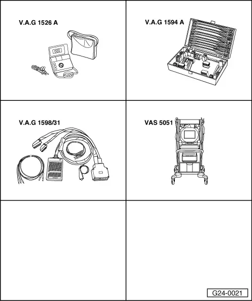
Special tools and workshop equipment required

  • ◆ V.A.G 1526 A
  • ◆ V.A.G 1594 A
  • ◆ V.A.G 1598/31
  • ◆ VAS 5051 with VAS 5051/1

or

  • ◆ V.A.G 1551 with V.A.G 1551/3 A

Fitting location => Fitting locations overview, Page 24-5

Test sequence

  • ‒ Connect vehicle diagnostic, testing and information system VAS 5051 (or fault reader V.A.G 1551). Select engine electronics control unit by entering the address word "01" ; when doing this the engine must be running at idling speed.
 
→ Indicated on display:
Rapid data transfer     HELP
Select function XX
  • ‒ Enter "08" to select the function "Read measured value block" and confirm entry with Q key.
 
→ Indicated on display:
Read measured value block    Q
Enter display group number XXX
  • ‒ Enter "004" to select Display Group 004 and confirm entry with Q key.
 
→ Indicated on display:
Read measured value block 4    ⇒
    1    2    3    4
  • ‒ Check display value for intake air temperature sender(display zone 4):

Display zones

1

2

3

4

Display Group 004: Intake air temperature with engine idling

Display

xxxx rpm

xx.x V

xxx.x °C

xxx.x °C

Indicates

Engine speed

Battery voltage

Coolant temperature

Intake air temperature

Range

0 ... 6800 rpm

10.0 ... 15.0 V

-48.0 ... 143.0 °C

-48.0 ... 143.0 °C

Specification

xxxx rpm

12.0 ...15.0 V

80.0 ...110.0 °C

Between ambient temperature and 110 °C 1)

1)    If there is a large difference between the temperature displayed and the ambient temperature at the sender, check the sender and sender wiring for contact resistance and open circuit.

 
V96-0749

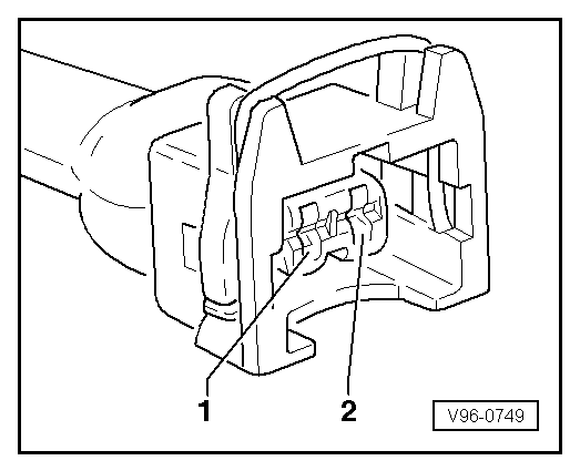
Checking wiring connections

  • ‒ Connect test box V.A.G 1598/31 to wiring harness for engine control unit. Do not connect to the engine control unit itself.
    => Page 24-20.
  • ‒ → Test for open circuit and short to positive or earth in the following wiring connections:

Connector
Contact

Test box V.A.G 1598/31
Socket

1

85

2

108

  • ‒ Test for short circuits between the two wires.
  • ‒ Rectify any open/short circuit as necessary.
 
A24-0040

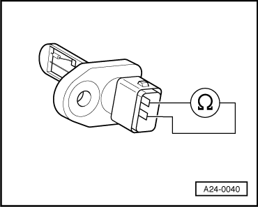
If no fault is detected in the wiring:

Testing sender

  • ‒ → Connect multimeter (resistance measurement range) to sender.

Specifications:

Temperature (°C)

Resistance (kω)

-20

approx. 13.8

0

approx. 5.5

20

approx. 2.4

40

approx. 1.1

60

approx. 0.6

If the specification is not attained:

  • ‒ Fit a new intake air temperature sender.

Testing engine speed sender -G28 > < Testing Motronic current supply relay -J271 - Vehicles from model year 2000 onwards