audi Workshop Repair Guides

Audi Workshop Service and Repair Manuals

Testing lambda probe heating -Z19 and -Z29 at lambda probes (before and after catalytic converter) > < Testing lambda probe (before catalytic converter) for ageing - engine code ANB
Motronic injection and ignition system (4-cyl. turbo)
Testing lambda control
Testing lambda probe and lambda control (after catalytic converter) - engine code ANB
 
N24-0957

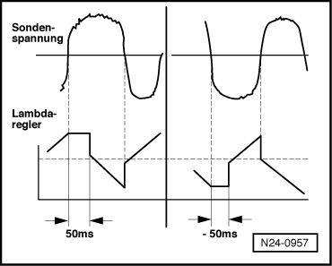
Note:

The lambda control function after (i.e. downstream of) the catalytic converter takes precedence over the lambda control before the catalytic converterand serves as a corrective regulation.

→ It corrects slight variations in the fuel mixture (e.g. an enriched mixture) originating from the lambda probe before the catalytic converter. It does so by holding the lambda control before the catalytic converter for a specified period of time (delay period) at the richest or leanest state. If the delay period is on the positive side (50 ms in the example), then the mixture will be enriched. Conversely, if the delay period is on the negative side (-50 ms in the example), the mixture will be made leaner.

 
A24-0240

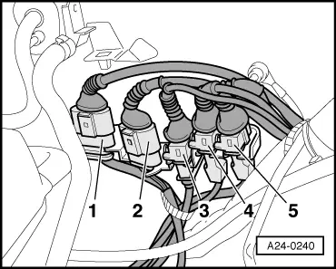
→ The 4-pin connector -1- (brown) for the lambda probe (after the catalytic converter) -G130 and lambda probe heating -Z30 is located underneath the coolant expansion tank.

 
G24-0024

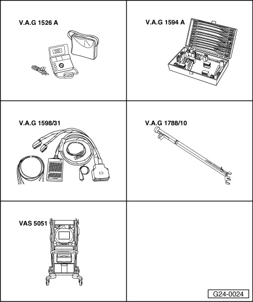
Special tools and workshop equipment required

  • ◆ V.A.G 1526 A
  • ◆ V.A.G 1594 A
  • ◆ V.A.G 1598/31
  • ◆ V.A.G 1788/10
  • ◆ VAS 5051 with VAS 5051/1

or

  • ◆ V.A.G 1551 with V.A.G 1551/3 A

Requirements for test:

  • ● Take the car for a test drive and do not erase the fault memory.
  • ● Coolant temperature at least 80 °C

Test sequence

  • ‒ Connect vehicle diagnostic, testing and information system VAS 5051 (or fault reader V.A.G 1551) and select engine electronics control unit by entering address word "01" ( .)
    When doing this the engine must be idling.
 
→ Indicated on display:
Rapid data transfer     HELP
Select function XX
  • ‒ Enter "04" to select "Basic setting" and confirm with Q key.

Note:

During the basic setting the activated charcoal filter solenoid valve (ACF valve -N80) is closed and the air conditioner compressor is switched off.

 
→ Indicated on display:
Introduction of basic setting    Q
Enter display group number XXX
  • ‒ Enter "034" for Display Group 034 and confirm entry with Q key.
 
→ Indicated on display:
System in basic setting 34    ⇒
    1    2    3    4
  • ‒ Set an engine speed of 2800...3200 rpm using speed regulator V.A.G 1788/10:
  • ‒ Continue the test as soon as an exhaust temperature of more than 350 °C is reached in display zone 2.

Note:

This process can take a few minutes.

  • ‒ Press C key.
  • ‒ Set an engine speed of 1800...2200 rpm using speed regulator V.A.G 1788/10:
 
→ Indicated on display:
Introduction of basic setting    Q
Enter display group number XXX
  • ‒ Enter "030" to select Display Group 030 and confirm entry with Q key.
 
→ Indicated on display:
System in basic setting    30    ⇒
    1    2    3    4    
  • ‒ Check status of lambda probe (after catalytic converter) in display zone 2.

Note:

The "lambda probe status" display indicates the status of the lambda control and lambda probes.

Display zones

1

2

3

4

Display Group 030: Lambda probe status at idling speed

Display

X X X

X X X

Display

Lambda probe status Bank 1, Probe 1

Lambda probe status Bank 1, Probe 2

Range

0 = off
1 = on

0 = off
1 = on


Specification

1 1 1

1 1 0

Note

If readout does not match specification => Page 24-100.

Relevance of 3-figure display in Display Group 030

X

X

X

Display zone 2

1

Lambda control active

1

Lambda probe condition

1

Status of lambda probe heating

Notes:

  • ◆ The lambda control of lambda probe (after the catalytic converter; B1-P2) is not active when the engine is not running under load.
  • ◆ The first digit of the three-digit display (heating) fluctuates between 0 and 1.

Testing lambda control (after catalytic converter)

  • ‒ Press C key.
 
→ Indicated on display:
Introduction of basic setting    Q
Enter display group number XXX
  • ‒ Enter "037" for Display Group 037 and confirm entry with Q key.
 
→ Indicated on display:
System in basic setting 37    ⇒
    1    2    3    4
  • ‒ Check lambda probe voltage in display zone 2:
  • ‒ Check the delay period of the lambda control (before the catalytic converter) in display zone 3 and the result of the diagnosis in display zone 4.

Display zones

1

2

3

4

Display group 037: Diagnosis of lambda control system

Display

xxx %

x.xxx V

xxx ms

---

Indicates

Engine load

Lambda probe voltage Bank 1, Probe 2

Delay period of lambda control (before catalytic converter), Bank 1

Status of diagnosis

Range

15...150 %

0.000...1.000 V

-800...800 ms

Test OFF
Test ON
SYST. O.K.
SYST. n. O.K.

Specification

15...35 %

0.100...0.900 V

-150...150 ms

SYST. O.K.

Note

If the specification is not attained, refer to "Reading display zone 2"=> Page 24-96

If the value increases to over 300 ms, this could indicate a leak in the exhaust system or a defective lambda probe.

If "SYST. n. O.K." appears on the display, interrogate fault memory
=> Page 01-9

Note on display zone 3:

The lambda control after the catalytic converter (downstream) takes precedence over the lambda control before the catalytic converter (upstream). The lambda control after the catalytic converter makes corrections in the mixture control process to compensate for slight variations in the fuel mixture (e.g. an enriched mixture) originating from the lambda probe before the catalytic converter. It does so by holding the lambda control before the catalytic converter for a specified period of time (delay period) at the richest or leanest state. If the delay period is on the positive side (50 ms in the example), then the mixture will be enriched. Conversely, if the delay period is on the negative side (50 ms in the example), the mixture will be made leaner.

Reading Display Group 037

Display zone 2

Possible cause of fault

Fault remedy

Approx. 0.450 V (constant)

- Open circuit in wire 4 between lambda probe and control unit

- Test basic voltage => Page 24-98

- Open circuit in wire 3 between lambda probe and control unit

More than 1.100 V

- Short to positive in wire 4 between lambda probe and control unit

- Test wiring of lambda probe (after the catalytic converter) => Page 24-99

Less than 0.150 V

- Short to earth in wire 4 between lambda probe and control unit

Further notes

If the readout in display zone 3 or 4 does not match the specification:

  • ‒ Take car for a test drive to free lambda probe of any deposits, then repeat the test.

If the readout in display zone 3 or 4 still does not match the specification even after the test drive:

  • ‒ Replace the lambda probe (before the catalytic converter) -G39.

Note:

If the lambda probe voltage is OK and the delay period for the lambda control after the catalytic converter is still above 1200 ms even after a test drive, this points to excessive ageing of the lambda probe before the catalytic converter.

 
A24-0240

→ Testing basic voltage

  • ‒ Unplug 4-pin connector -1- (brown) for lambda probe (after catalytic converter) -G130.

 
A24-0094
  • ‒ → Connect multimeter (voltage measurement range) between contacts 3 and 4.
  • ‒ Switch ignition on.
    • ‒ Specification: 0.400 ... 0.500 V
  • ‒ Switch off ignition.

If the specification is not obtained:

  • ‒ Test lambda probe wiring.

If the specification is obtained:

  • ‒ Replace the lambda probe (after catalytic converter) -G130.
 
A24-0240

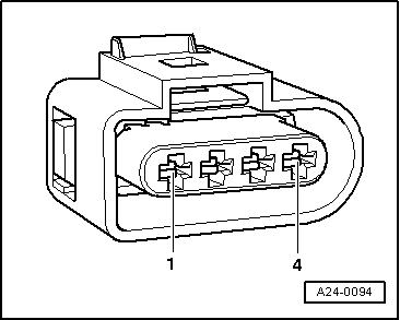
Testing lambda probe wiring

  • ‒ Unplug 4-pin connector -1- (brown) for lambda probe (after catalytic converter) -G130.
  • ‒ Connect test box V.A.G 1598/31 to wiring harness for engine control unit. Do not connect to the engine control unit itself.
    => Page 24-20.

 
A24-0094
  • ‒ → Test the following wiring connections for open circuits:

Connector
Contact

Test box V.A.G 1598/31
Socket

3

68

4

69

  • ‒ Rectify any open circuits.
  • ‒ Test for short circuits between the wires.

If the wiring is OK:

  • ‒ Fit a new engine control unit => Page 24-24.

Testing lambda probe heating -Z19 and -Z29 at lambda probes (before and after catalytic converter) > < Testing lambda probe (before catalytic converter) for ageing - engine code ANB