audi Workshop Repair Guides

Audi Workshop Service and Repair Manuals

Removing and installing Lambda probe > < Testing lambda probe and lambda control (after catalytic converter) - engine code ANB
Motronic injection and ignition system (4-cyl. turbo)
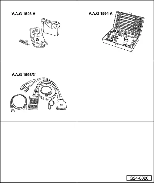
Testing lambda control
Testing lambda probe heating -Z19 and -Z29 at lambda probes (before and after catalytic converter)
 
G24-0020

Special tools and workshop equipment required

  • ◆ V.A.G 1526 A
  • ◆ V.A.G 1594 A
  • ◆ V.A.G 1598/31

Requirements for test:

  • ● Coolant temperature at least 80 °C
  • ● Fuse for lambda probe heating OK

=> Current flow diagrams, Electrical fault finding and Fitting locations binder

 
A24-0240

Test sequence

Vehicles with engine code letters APU:

  • ‒ → Unplug 4-pin connector -2- (black) for lambda probe (before catalytic converter) -G39.

Models with engine code letters ANB:

  • ‒ Unplug 4-pin connector -1- (brown) for lambda probe (after catalytic converter) -G130.

 
A24-0088

All models

  • ‒ → Connect multimeter (resistance measurement range) between contacts 1 and 2.
    • ‒ Specification: 1 ... 5 ω(at room temperature)

Note:

The resistance will increase sharply at higher temperatures.

If the specification is not attained:

  • ‒ Renew the lambda probe.

If the specification is obtained:

  • ‒ Test voltage supply for lambda probe heating
    .
 
A24-0094

Testing voltage supply for lambda probe heating

  • ‒ → Connect multimeter (voltage measurement range) between contacts 1 (positive) and 2 (earth).
  • ‒ Start the engine.
    • ‒ Specification: approx. battery voltage (may fluctuate)

Notes:

  • ◆ At certain points during operation, the engine control unit intervenes by constantly connecting and disconnecting the earth connection for lambda probe heating. For this reason the voltage displayed on the tester may fluctuate.
  • ◆ If required, observe Display Group 041 in the "Read measured value block" function to find out when the engine control unit is switching the lambda probe heating on and off.

If no voltage is present:

  • ‒ Connect multimeter (voltage measurement range) as follows:

Connector
Contact

Measure against

1 (positive)

Vehicle earth

  • ‒ Operate starter briefly.
    • ‒ Specification: approx. battery voltage

If there is still no voltage reading:

  • ‒ Test for open circuit in wiring connection between fuel pump relay and contact 1 on connector via fuse S234 (at socket position 34):

=> Current flow diagrams, Electrical fault finding and Fitting locations binder

 
A24-0094

If the voltage supply is OK:

  • ‒ → Connect multimeter (voltage measurement range) as follows:

Connector
Contact

Measure against

2 (switched earth
connection from engine control unit)

Battery positive

  • ‒ Start the engine.
    • ‒ Specification: approx. battery voltage (may fluctuate)
  • ‒ Switch off ignition.
 
A24-0094

If no voltage is present:

  • ‒ Connect test box V.A.G 1598/31 to wiring harness for engine control unit. Do not connect to the engine control unit itself.
    => Page 24-20.
  • ‒ → Test for open circuits in the following wiring connection:

Lambda probe heating -Z19 for lambda probe (before catalytic converter):

Connector
Contact

Test box V.A.G 1598/31
Socket

2

5

Lambda probe heating -Z29 for lambda probe (after catalytic converter) - only for engines with engine code ANB:

Connector
Contact

Test box V.A.G 1598/31
Socket

2

63

  • ‒ Rectify any open circuits.

If the wiring connection is O.K. but the lambda probe heating still has no earth connection:

  • ‒ Fit a new engine control unit => Page 24-24.

Removing and installing Lambda probe > < Testing lambda probe and lambda control (after catalytic converter) - engine code ANB