audi Workshop Repair Guides

Audi Workshop Service and Repair Manuals

Testing intake air temperature sender -G42 (AEB engine only) > < Checking knock senders -G61 and -G66
Motronic Injection and Ignition System (4 cyl.)
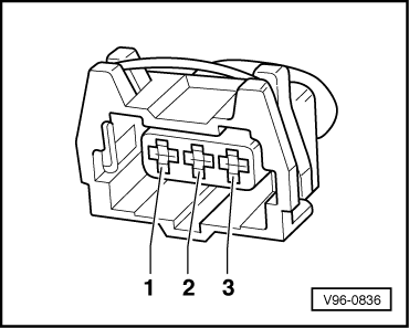
Checking Hall sender -G40

The Hall sender is located in the distributor on ADP engines and on ADR / AEB engines at the front of the cylinder head, see Fitting locations overview .

Notes:

  • ◆ In normal operation the engine control unit recognises the ignition position for cylinder 1 from the Hall sender signal
  • ◆ If no Hall sender signal is received, the knock sensor signals can no longer be assigned to the cylinders. If this happens, the knock control system is deactivated and the ignition timing is slightly retarded in order to prevent knocking.
  • ◆ In the event of failure of the Hall sender all three engine variants continue to run and can also be re-started for the following reasons:

The fact that the control unit is out of phase by one engine revolution does not have any noticeable effect on the injection system. If this happens, the fuel is injected "upstream" (before the closed inlet valve) instead of while the inlet valve is open. This has only a minor influence on the quality of the air/fuel mixture.

    • ‒ With the distributor system of the ADP engine the cylinder allocation takes place mechanically via the distributor.
    • ‒ With the double spark system of the ADR engine, there is a spark for each cylinder on every engine revolution (and not just on every second revolution as is otherwise normal).
    • ‒ On the ignition system of the AEB engine with four individual ignition coils, the Motronic control unit triggers a spark on every cylinder for every revolution of the engine once this fault has been detected.
 
96-836
  • ‒ Push back rubber grommet at connector of the Hall sender (the connector remains plugged in at the sender).
  • ‒ → Connect diode test lamp V.A.G 1527 from rear between contacts 1 and 2.

Note:

Receptacles are numbered accordingly on the back of the connector.

  • ‒ Operate starter for a few seconds.
  • ‒ The diode test lamp must flash briefly on each second engine revolution.
  • ‒ Pull connector off Hall sender.
  • ‒ Switch ignition on.
  • ‒ Connect hand-held multimeter V.A.G 1526 to contacts 1 and 3 of the connector of the Hall sender..
  • ‒ Specified value: 4.5 ... 5.5 V
  • ‒ Connect hand-held multimeter V.A.G 1526 to contacts 2 and 3 of the connector of the Hall sender..
  • ‒ Specified value: Battery voltage
 
96-836
  • ‒ If the specified values are achieved and the diode test lamp does not flash, replace the Hall sender.
  • ‒ If the specified values are not achieved test the wiring as follows:
  • ‒ Connect test box V.A.G 1598/19 to the wiring harness of the Motronic control unit.
  • ‒ → Check the wiring from the Hall sensor ....

 
24-1193
  • ‒ → ... to Motronic control unit -J220 for open circuit and short to positive or ground according to current flow diagram.

Contact on connector for Hall sensor

Test box V.A.G 1598/19 or -J220

1

A3 (positive, 5 V)

2

B2 (signal)

3

A15 (ground from control unit)

  • ‒ If a trial erasure of the fault memory is followed by the replaced indication of a fault relating to the camshaft sensor (Hall sender) although all previous tests were OK, the following faults are possible:
    • ‒ ADP engine
      Distributor rotated or incorrectly fitted.
      Test and adjust basic setting => Page 28-9.
    • ‒ ADR or AEB engine
      rotor ring for Hall sender rotated.
  • ‒ Unbolt the Hall sensor, then check to ensure that the rotor ring is correctly aligned on the camshaft.(if it is incorrectly installed, the catch will be pressed flat when the securing screw is tightened).
  • ‒ If the position of rotor ring is OK, check the position of the camshaft in relation to the crankshaft.

=> 4-cylinder engine, Mechanics; Repair Group 13; Dismantling and reassembling engine; Removing and installing toothed belt, tensioning.

Note on signal testing with an oscilloscope:

The centre point of the window of the Hall sender must lie on the third falling flank of the engine speed signal after the reference mark gap.

Testing intake air temperature sender -G42 (AEB engine only) > < Checking knock senders -G61 and -G66