audi Workshop Repair Guides

Audi Workshop Service and Repair Manuals

Checking auxiliary signals > < Checking air mass meter -G70
Motronic Injection and Ignition System (4 cyl.)
Testing control unit input values
Testing altitude sender - engine code AEB

The signal from the altitude sender influences

  • ◆ the boost pressure control
  • The boost pressure control prevents the turbocharger from over-revving when the altitude increases and consequently the air density decreases.
  • Due to the reduction in air density (reduction in air pressure), the turbocharger needs to work harder (higher rotational speed) to deliver the required boost pressure.
  • This results in a higher charge air temperature and an increased risk of engine knocking. To avoid this, the boost pressure is limited.
  • ◆ Mixture composition during engine start:
  • The richness of the starting mixture is preset by map data in the Motronic control unit and corrected with increasing altitude (decreasing air density due to decreasing air pressure) by a "lean" adjustment determined by the altitude sender.

Note:

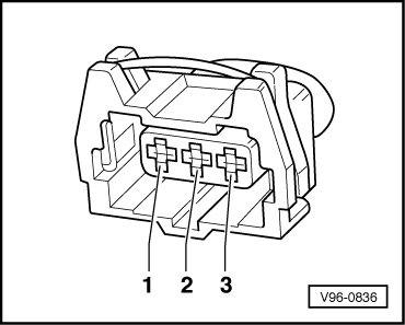
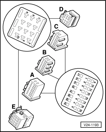
The altitude sender is located in the electronics box next to the Motronic control unit.

Testing altitude sender signal

  • ‒ Read individual measured value (function 09) and select channel 06.
 
→ Display:
Read individual measured value    ⇒
Channel 06    measured value    193

Specifications:

Altitude:
in m

Air pressure in mbar

Signal voltage

Channel 06
Measured value

0

1013

4.0 V

204

400

970

3.7 V

188

1000

900

3.0 V

153

2000

800

2.1 V

107

3000

700

1.3 V

66

Pressure variations due to weather changes are not taken into account.

  • ‒ Measure the current air pressure using turbocharger tester V.A.G 1597/A (absolute pressure display) and compare it to the measured value from channel 06.
  • ‒ If the measured value from channel 06 deviates so much that it seems implausible for the altitude / air pressure, check the wiring for contact resistance and if necessary, replace the altitude sender.

Checking wiring

Note:

The altitude sender is monitored by the self-diagnosis system =>Fault table, fault code 00528 - Page

 
96-836
  • ‒ Disconnect the plug from the altitude sender.
  • ‒ → Measure the voltage with a hand-held multimeter V.A.G 1526 in turn between the contacts 1 + 3 and 2 + 3.

Specified value: 4.5...5.5 V in each case

  • ‒ If one of the specified values is not met turn off the ignition.
  • ‒ Connect test box V.A.G 1598 with adapter cable V.A.G 1598/19 to the wiring harness for the Motronic control unit.
 
96-836
  • ‒ → Check the following wiring connections for continuity and short circuits according to the current flow diagram:

3-pin connector,
contact

V.A.G 1598/19,
socket

1

C9

2

C6

3

C2

 
24-1193
  • ‒ → If necessary rectify open circuit or short circuit according to the current flow diagram
  • ‒ If the wiring is OK replace the altitude sensor.
  • ‒ If after replacing the altitude sensor an implausible value is obtained again, replace the Motronic control unit.

Checking auxiliary signals > < Checking air mass meter -G70