audi Workshop Repair Guides

Audi Workshop Service and Repair Manuals

Checking Hall sender -G40 > < Checking coolant temperature sender -G62
Motronic Injection and Ignition System (4 cyl.)>06.96
Checking knock senders -G61 and -G66

On ADP engines only one knock sensor is fitted (-G61).

Notes:

  • ◆ It is not possible to carry out an electrical test of the knock sensors themselves.
  • ◆ Interrogate fault memory .
  • ◆ Read measured value block, Display groups 15 and 16
  • ◆ To ensure that the knock sensors function properly it is important to keep exactly to the specified tightening torque of 20 Nm.
  • ◆ Check plug connection from knock sensor to wiring harness for corrosion (plug connections are located behind the coolant expansion tank).
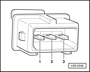
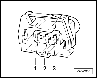
  • ‒ Connect test box V.A.G 1598 with adapter cable V.A.G 1598/19 to the wiring harness for the Motronic control unit.
  • ‒ Disconnect the plug for the relevant knock sensor (behind coolant expansion tank).
 
28-546
  • ‒ → Check all three contacts on the knock sensor connector for short circuit to each other using an ohmmeter. The must be no connection between any of the wires.
  • ‒ If there is a connection between the contacts, fit a new knock sensor.

Testing wiring from knock sensor to Motronic control unit

  • ‒ Connect test box V.A.G 1598/19 to the wiring harness of the Motronic control unit.
 
96-836
  • ‒ → Check wiring from the relevant sensor connector ...
 
24-1193
  • ‒ → ... to Motronic control unit -J220 for open circuit and short to positive or ground according to current flow diagram.

Contact on sender connector

Test box V.A.G 1598/19 or -J220

-G61
1
2
3


A8 (signal)
A15 (reference ground)
D11 (screening to ground)

-G66
1
2
3


A16 (signal)
A15 (reference ground)
D11 (screening to ground)

Note:

Use only gold plated contacts when repairing the contacts in the plug connectors for the knock sensors.

Checking Hall sender -G40 > < Checking coolant temperature sender -G62