audi Workshop Repair Guides

Audi Workshop Service and Repair Manuals

Checking air mass meter > < Testing injection quantity, leak-tightness and spray pattern of injectors
Motronic injection and ignition system (6-cylinder)
Servicing Motronic injection system
Testing fuel pump relay and activation

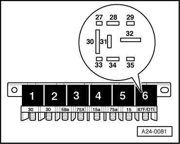
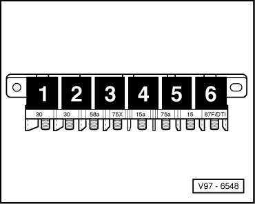
The fuel pump and some of the injection system components are powered via the fuel pump relay -J17.

The fuel pump relay -J17 will only close if the engine is turning over. In other words, the relay is only earthed (via the engine control unit) when the engine control unit is receiving engine speed impulses.

Test conditions

  • ● Battery voltage at least 11 V

Special tools, testers and auxiliary items

  • ◆ Hand multimeter V.A.G 1526 or V.A.G 1526 A
  • ◆ Fault reader V.A.G 1551 (or vehicle system tester V.A.G 1552) with cable V.A.G 1551/3
  • ◆ Adapter set V.A.G 1594
  • ◆ Test box V.A.G 1598/22

Testing operation of fuel pump relay

  • ‒ Connect fault reader V.A.G 1551
    .
  • ‒ Switch on ignition.
  • ‒ Start final control diagnosis and select one of the injectors
    => Page 01-79.
 
A24-0081
  • → The fuel pump relay (central electrics, relay position 6) should pick up...
  • ‒ If the relay does not pick up, test activation of fuel pump relay
    .
  • ...and the fuel pump should run.
  • ‒ If fuel pump does not run, test activation of fuel pump and other components .

Testing activation of fuel pump relay

  • ‒ Switch off ignition.
  • ‒ Connect test box V.A.G 1598/22 to wiring harness for engine control unit => Page 24-24.
 
V97-6548
  • ‒ Connect sockets 2 and 4 of test box to each other using auxiliary cable from V.A.G 1594.
  • ‒ Switch ignition on.
  • → Specification: The fuel pump relay (central electrics, relay position 6) should pick up.

If the relay picks up now but not during the final control diagnosis:

  • ‒ Fit a new engine control unit.

If the relay does not pick up:

  • ‒ Switch off ignition.
 
A24-0081
  • ‒ → Disconnect fuel pump relay from relay panel (central electrics, relay position 6).
  • ‒ Connect multimeter (voltage measurement range) between earth and contact 28 on relay panel.
  • ‒ Switch ignition on.
    • ‒ Specification: approx. battery voltage

If the specification is not attained:

  • ‒ Check the wiring.

=> Current flow diagrams, Electrical fault-finding and Fitting locations

If the specification is attained:

  • ‒ Switch off ignition.
 
A24-0081
  • ‒ → Test for open circuit and short to positive or earth in the following wiring connections:

Central electrics, relay position 6, contact

Socket on test box V.A.G 1598/22

16

4

  • ‒ Rectify any open/short circuit as necessary.

If no fault in wire is detected:

  • ‒ Fit a new fuel pump relay -J17.

Testing activation for fuel pump and other components

 
A97-0119
  • ‒ → Remove fuses 28, 29 and 34.
  • ‒ Start final control diagnosis and select one of the injectors
    => Page 01-79.
  • ‒ Connect multimeter (voltage measurement range) between earth and the left-hand or right-hand contact on the following fuses:

Fuse No.

Specification for left-hand or right-hand contact

28

approx. battery voltage

29

approx. battery voltage

34

approx. battery voltage

If the specification is not attained:

  • ‒ Check wiring

=> Current flow diagrams, Electrical fault-finding and Fitting locations

If no fault in wire is detected:

  • ‒ Fit a new fuel pump relay -J17.

Checking air mass meter > < Testing injection quantity, leak-tightness and spray pattern of injectors