audi Workshop Repair Guides

Audi Workshop Service and Repair Manuals

Removing and installing Lambda probe > < Checking lambda probe heating
Motronic injection and ignition system (6-cylinder)
Testing lambda control
Testing lambda probe signal wiring and activation

Note:

The lambda probe signal is monitored by the self-diagnosis system.

Special tools, testers and auxiliary items

  • ◆ Hand multimeter V.A.G 1526 or V.A.G 1526 A
  • ◆ Fault reader V.A.G 1551 (or vehicle system tester V.A.G 1552) with cable V.A.G 1551/3
  • ◆ Adapter set V.A.G 1594
  • ◆ Test box V.A.G 1598/22
  • ‒ Connect fault reader V.A.G 1551
    .
  • ‒ Switch on ignition.
  • ‒ Interrogate fault memory.
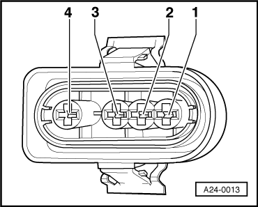
  • ‒ If a fault relating to the lambda probe is indicated on the display and the lambda probe heating is OK, unplug the lambda probe connector for the left-hand or right-hand cylinder bank.
    Fitting locations=>Pages 24-6.
 
A24-0013
  • ‒ → Test voltage by connecting hand-held multimeter V.A.G 1526 (measuring range 2 V) between contacts 3 and 4 of plug on wiring harness.
  • ‒ Switch ignition on.
    • ‒ Specification: 450±50 mV
  • ‒ If the reading matches the specification, fit a new lambda probe.
  • ‒ If the reading is not as specified, connect test box 1598/22 to the wiring harness for the engine control unit .
 
A28-0022
  • ‒ → Test for open circuit and short to positive or earth in the following wiring connections:

Lambda probe Bank 1 -G39

Contact on wiring
harness plug

Test box V.A.G 1598/22 or -J220

3

25

4

26

Lambda probe Bank 2 -G108

Contact on wiring
harness plug

Test box V.A.G 1598/22 or -J220

3

39

4

40

  • ‒ Rectify any open/short circuit as necessary.
  • ‒ If the wiring is OK, fit a new engine control unit
    .

Removing and installing Lambda probe > < Checking lambda probe heating