
Checking Hall sender for A4 Mk1 power unit ignition
 |
|
|
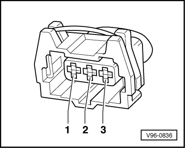
Checking activation of Hall sender For following checks, use leads from adapter set V.A.G 1594.
Note: Receptacles are numbered accordingly on the back of the connector.
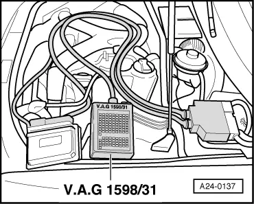
The diode test lamp must flash briefly on each second engine revolution. Note: Diode test lamps with a low current draw continue to glow faintly between impulses from the engine control unit (rather than going out completely) and become much brighter when receiving an impulse. If diode test lamp does not flash, check voltage supply. Checking the power supply for the Hall sender.
|
|
|
Checking signal line for Hall sender:
Checking earth line for Hall sender: |
|
|||||||||||||||||
Hall sender (bank 2)
Hall sender (bank 1)
Checking phase location of Hall sender
|
| → Display: |
|
||
|
| → Display: |
|
||
|
| → Display: |
|
||||||||||||||||||||||||||||||||||||||||
| |||||||||||||||||||||||||||||||||||||||||