audi Workshop Repair Guides

Audi Workshop Service and Repair Manuals

Checking Hall sender > < Checking knock control stop
Motronic injection and ignition system (6 cyl. turbo)
Checking ignition system
Checking knock sensors

Notes:

  • ◆ The knock sensors -G61 and -G62 cannot themselves be tested electrically.
  • ◆ Use only gold-plated contacts when repairing the cable connectors for the knock sensors.
  • ◆ To ensure that the knock sensors function properly it is important to keep exactly to the specified tightening torque of 20 Nm.
  • ◆ Check connector between knock sensor and wiring harness for corrosion.
 
N28-0109

Checking knock sensors

  • ‒ → Disconnect the connector for the relevant knock sensor in the engine compartment.

Note:

  • ◆ Installation locations OverviewPage 24-5.
  • ◆ In order to reach the connector of the knock sensor for bank 2, the coolant reservoir securing bolts must be removed and the reservoir moved to one side. Do not detach hoses.
 
A28-0029
  • ‒ → Test for short between all three contacts in the knock sensor connector (contacts 1+2, 1+3, 2+3).
  • Specified value: The must be no connection between any of the wires (infinite resistance).
  • ‒ If there is a connection between the contacts, fit a new knock sensor.

Notes:

  • ◆ In order to reach the knock sensor, the air duct must be removed, =>Page 24-45.
  • ◆ Use special tool 3247 to remove the knock sensors.
 
A24-0137
  • ‒ If no short is found, check knock sensor wiring.

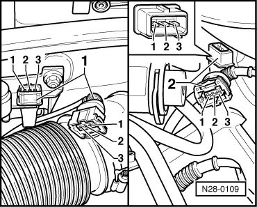
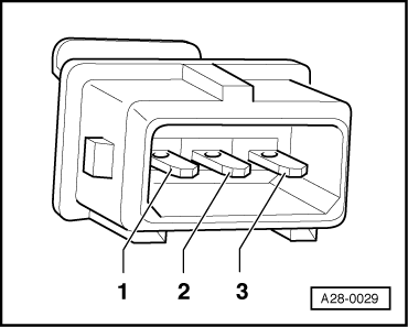
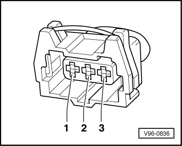
Checking wiring from knock sensors to engine control unit

  • ‒ → Connect V.A.G 1598/31 test box to wiring harness leading to engine control unit; the engine control unit should not be connected =>Page 24-22.
 
V96-0836
  • ‒ → Check wiring from the relevant sensor connector ...

 
A24-0137
  • ‒ → ...to engine control unit for open circuit and short to positive or earth.

Knock sensor 1 - G61 (bank 1)

3-pin connector on wiring harness, contact

Test box V.A.G 1598/31 or engine control unit

1 (earth)

99

2 (signal)

106

3 (screening)

108

Knock sensor 2 -G61 (bank 2)

3-pin connector on wiring harness, contact

Test box V.A.G 1598/31 or engine control unit

1 (earth)

99

2 (signal)

107

3 (screening)

108

  • Wire resistance: max. 1.5 Ohm
  • ‒ Rectify any open/short circuit as necessary.

Checking Hall sender > < Checking knock control stop