audi Workshop Repair Guides

Audi Workshop Service and Repair Manuals

Checking intake air system for leaks (unmetered air) > < Testing fuel pump relay and activation
Motronic injection and ignition system (6 cyl. turbo)
Servicing Motronic injection system
Testing air mass meter

Test conditions

  • ● Coolant temperature at least 80 oC (display group 4, display zone 3).
  • ● Electrical consumers switched off (radiator fan must not run during the check)
  • ● Air conditioner switched off
  • ● Fuse for airflow meter OK.

=> Current Flow Diagrams, Electrical Fault-Finding and Fitting Locations

checking function

  • ‒ Connect up vehicle diagnostic, testing and information system VAS 5051 or fault reader V.A.G 1551 and select engine electronics control unit with "Address word" 01 .
    For this purpose, the engine must be running at idle speed
 
→ Display:
Rapid data transfer     HELP
Select function XX
  • ‒ Press keys 0 and 4 for the function "Introduction of basic setting" and confirm entry with Q key.

Note:

During basic setting, the solenoid valve for the active carbon canister (valve N80) is closed and the air conditioner compressor is switched off by the engine control unit.

 
→ Display:
Initiate basic setting    HELP
Enter display group number XXX
  • ‒ Press keys 0, 0 and 2 for "display group 2" and confirm entry with Q key.
 
→ Display:
Basic setting 2    ⇒
    1    2    3    4
  • ‒ Check specified results for recorded load.

Display zones

1

2

3

4

Display group 2: Intake airflow at idle and operating temperature

Display

xxx rpm

xx.x %

x.x ms

xxx.x g/s

Display

Engine speed
(in steps of 40 rpm)

Load

Average injection period

Air mass

Range

min.: 750 rpm
max.: 7200 rpm

min.: 15 %
max.: greater than 175 %

min.: 2.0 ms
max.: 19.0 ms

min.: 3.0 g/s
max.: approx. 225 g/s

Specified value

750...850 rpm

15.0...25.0 %

2.0...4.0 ms

3.0...40.5 g/s

Note:

---

---

If specified value is not attained: Evaluation, display zone 3
=> Page 24-65

If specified value is not attained: Evaluation, display zone 4
=> Page 24-66

If specified value is attained:

  • ‒ Press the ⇒key.
  • ‒ Press keys 0 and 6 for the "End output" function and press the Q key to confirm entry.
  • ‒ Switch ignition off.

Interpreting display group 2

Display zone: 3

Possible causes of fault

Fault remedy

Less than 2.0 ms

- Lower values can only occur when vehicle is on overrun

Greater than 4.0 ms

- Engine load from ancillaries

- Eliminate load (air conditioner system/ power steering/alternator)

- Poor idling (not running on all cylinders)

- Test spark plugs
Check injectors

- Throttle valve control unit -J338 defective

- Check throttle valve control unit => Page 24-141

Interpreting display group 2

Display zone: 4

Possible causes of fault

Fault remedy

Less than 3.0 g/s

- Large quantity of unmetered air between intake manifold and airflow meter
- Voltage supply to airflow meter or wiring to engine control unit

- Test for leaks (unmetered air) in intake air system

Greater than 4.5 g/s

- Engine load from ancillaries

- Eliminate load (air conditioner system/ power steering/alternator)

- Voltage supply to airflow meter or wiring to engine control unit

- Check voltage supply and/or wiring => Page 24-67

Testing voltage supply to air mass meter

 
A23-0058
  • ‒ → Disconnect connector from air mass meter.
  • ‒ Connect hand-held multimeter (voltage test range) between engine earth and contact 2 on the connector.
  • ‒ Operate the starter briefly.
  • Specified value: approx. battery voltage

Note:

Voltage supply to airflow meter is from fuel pump relay.

If battery voltage is not present:

  • ‒ Test wiring from contact 2 on connector via fuse to fuel pump relay for open circuit or short to earth. Rectify if necessary.

=> Current Flow Diagrams, Electrical Fault-Finding and Fitting Locations

 
A23-0058
  • ‒ → Connect hand-held multimeter to contact 2 and contact 3 of the connector to measure voltage.
  • ‒ Operate the starter briefly.
  • Specified value: approx. battery voltage

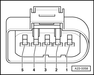
Note:

Engine control unit earth is present at contact 3 of the connector.

If specified value is not attained, check wiring => Page 24-69.

 
A23-0058
  • ‒ → Connect hand-held multimeter to contact 3 and contact 4 of the connector to measure voltage.
  • ‒ Switch the ignition on.
  • Specified value: approx. 5 V.

If specified value is not attained, check wiring => Page 24-69.

Check wiring to airflow meter.

Note:

The signal wire is also checked during the wiring check.

  • ‒ Connect the V.A.G 1598/31 test box to wiring harness leading to engine control unit; the engine control unit should not be connected => Page 24-22.

The following wiring connections are to be checked for open circuits and/or short to positive or negative.

 
A23-0058

Connector for airflow meter -G70

Test box V.A.G 1598/31 Contact

3

27

4

53

5

29

  • Wire resistance: max. 1.5 Ohm
  • ‒ Additionally check all wires for short to one another.
  • Specified value: infinite resistance (open circuit)
  • ‒ If the voltage supply and the wiring are OK, renew the airflow meter (G70).

Checking intake air system for leaks (unmetered air) > < Testing fuel pump relay and activation