
A4 Mk1
|
Checking ignition system
Checking engine speed sender -G28
|
 |
|
|
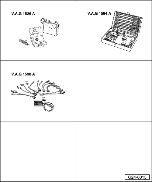
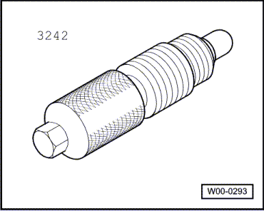
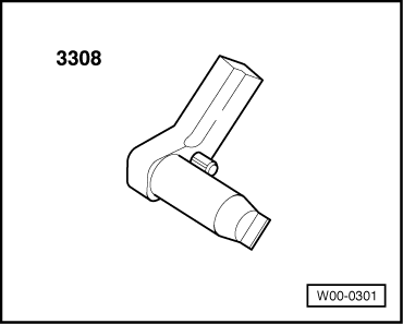
Special tools and workshop equipment required
Installation position => Installation position overview - Page 24-5
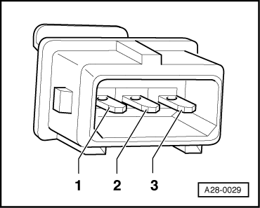
Checking internal resistance
|
 |
|
If the specification is not obtained:
If specified values are not obtained:
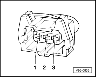
Checking wiring |
 |
|
|
 |
||||||||
=> "Current Flow Diagrams, Electrical Fault Finding and Fitting Locations" binder If no wiring fault is detected:
=> Electrical system; Repair group 27; Removing and installing starter
If no fault is found:
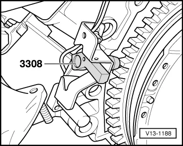
Adjusting holder for engine speed sender Notes:
|
 |
|
Special tools and workshop equipment required
|
 |
|
Work sequence |
 |
|
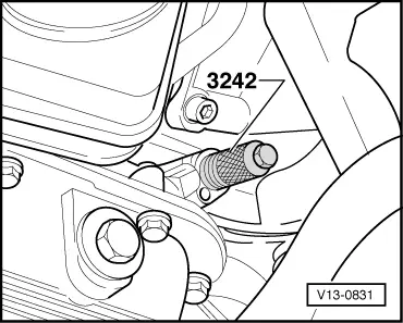
Note: TDC hole is located exactly behind the sender in the crankshaft (can be felt). Attention:
To avoid possible injury, never turn crankshaft whilst feeling for TDC. |
 |
|
|
 |
|
The remaining installation steps are carried out in the reverse sequence: |