audi Workshop Repair Guides

Audi Workshop Service and Repair Manuals

Checking engine speed sender -G28 > < Checking output stage -N122
MPFI Fuel Injection and Ignition System
Checking ignition system
Checking ignition timing sender -G4
 
G24-0015

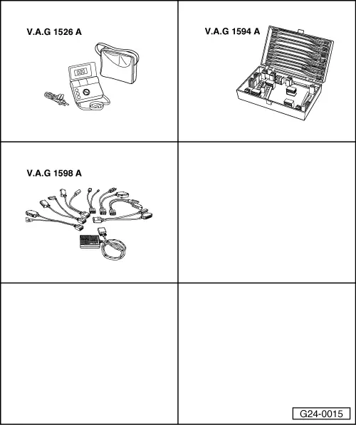
Special tools and workshop equipment required

  • ◆ V.A.G 1526 A
  • ◆ V.A.G 1594 A
  • ◆ V.A.G 1598 A
  • ◆ V.A.G 1598/11

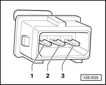
Installation position => Installation position overview - Page 24-5

  • ‒ Before carrying out the test, make sure that the sender is correctly installed and firmly seated.

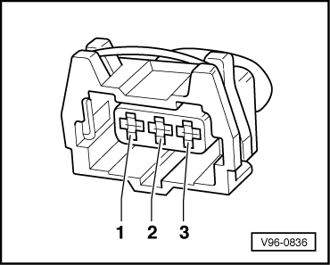
Checking internal resistance

  • ‒ Pull black 3-way connector off ignition timing sender.
 
A28-0029
  • ‒ → Connect multimeter between contacts 1 and 2 on sender to measure resistance.
    • ‒ Specification: approx. 1 kω

If the specification is not obtained:

  • ‒ Replace ignition timing sender.
  • ‒ Connect multimeter between contacts 1 and 3 and 2 and 3 on sender to measure resistance.
    • ‒ Specification: ∞ ω (no continuity)

If specified values are not obtained:

  • ‒ Replace ignition timing sender.

Checking wiring

 
A87-0016
  • ‒ → With the ignition switched off, use adapter V.A.G 1598/11 to connect test box V.A.G 1598 A to connector B only of engine control unit (control unit remains disconnected) .
 
V96-0836
  • ‒ → Check for open circuit and short to earth/positive or earth in the following wiring connections:

Connector
Contact

Test box V.A.G 1598 A
Socket

1 (earth)

35

2 (signal)

39

3 (screening)

34

  • ‒ Rectify any open/short circuit as necessary.

=> "Current Flow Diagrams, Electrical Fault Finding and Fitting Locations" binder

If no fault is found:

  • ‒ Replace engine control unit => Page 24-12.

Checking engine speed sender -G28 > < Checking output stage -N122