-
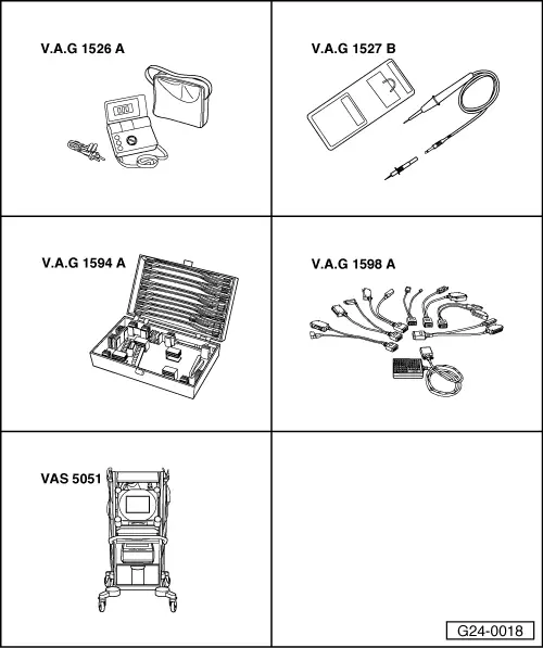
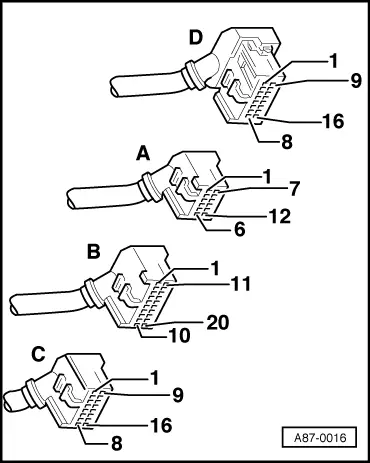
‒ → With the ignition switched off, use adapter V.A.G 1598/11 to connect test box V.A.G 1598 A to connector B and additionally to the engine control unit => Page 24-9.
-
‒ Connect voltage tester V.A.G 1527 B as follows:
|
|
|---|
|
Test box V.A.G 1598 A
Socket
|
Measure to
|
|
23
|
Engine earth
|
-
‒ Switch on ignition.
-
‒ Depress the brake pedal and engage a gear.
-
‒ The LED must light up when a gear is engaged.
If the LED does not light up:
-
‒ Pull connector B off adapter V.A.G 1598/11.
If the LED still does not light up (irrespective of selector lever position):
-
‒ Replace engine control unit .
If the LED then lights up:
-
‒ Check the following wiring for short to earth:
|
|
|---|
|
Test box
V.A.G 1598 A
Socket
|
Control unit for
Automatic gearbox
Contact
|
|
23
|
=> "Current Flow Diagrams, Electrical Fault Finding and Fitting Locations" binder
|
-
‒ If wiring is OK, establish defect in multi-function switch -F125.
If the LED lights up with connector B attached and does not switch off on engaging "P" or "N":
-
‒ Check for open circuit in the following wiring connections:
|
|
|---|
|
Test box
V.A.G 1598 A
Socket
|
Control unit for
Automatic gearbox
Contact
|
|
23
|
=> "Current Flow Diagrams, Electrical Fault Finding and Fitting Locations" binder
|
-
‒ If wiring is OK, establish defect in multi-function switch -F125.
|