audi Workshop Repair Guides

Audi Workshop Service and Repair Manuals

Checking idling switch -F60 > < Checking activated charcoal filter system solenoid valve 1 -N80
MPFI Fuel Injection and Ignition System
Checking throttle valve potentiometer -G69
 
G24-0015

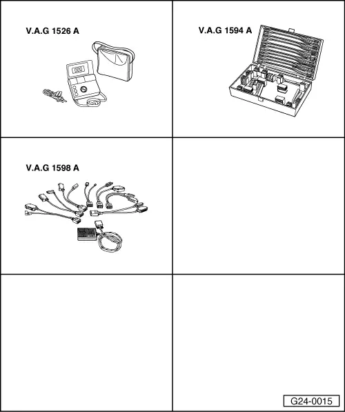
Special tools and workshop equipment required

  • ◆ V.A.G 1526 A
  • ◆ V.A.G 1594 A
  • ◆ V.A.G 1598 A
  • ◆ V.A.G 1598/11

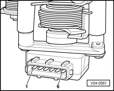
Installation position => Installation position overview - Page 24-5

Notes:

  • ◆ The throttle valve potentiometer (G69) informs the engine control unit of the position of the throttle valve.
  • ◆ Checking function=> Reading measured value block display group 002, Page 01-62.
  • ◆ After switching off ignition, engine control unit enters self-holding phase for 150 minutes. If repairs to throttle valve potentiometer are performed during this period, a fault may be stored in the fault memory.

Checking internal resistance

  • ‒ Pull connector off throttle valve potentiometer.
 
V24-0561
  • ‒ → Connect multimeter between contacts 1 and 2 to measure resistance.
    • ‒ Specification: 1.5 ... 2.6 kω
  • ‒ Connect multimeter between contacts 2 and 3 to measure resistance.
    • ‒ Specification: 0.75 ... 1.3 kω
  • ‒ Slowly move the throttle valve lever to full throttle position.
    • ‒ Specification: Increasing resistance up to max. 3.6 kω

If a specification is not met:

  • ‒ Replace throttle valve potentiometer.

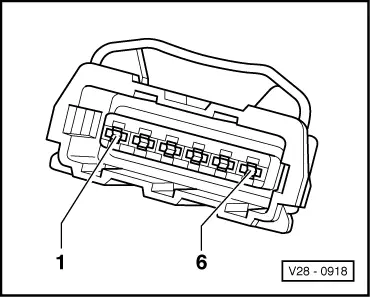
Checking power supply

  • ‒ Pull connector off throttle valve potentiometer.
  • ‒ Switch on ignition.
 
V28-0918
  • ‒ → Connect multimeter between contacts 1 and 2 to measure resistance.
    • ‒ Specification: 4.5 ... 5.5 V
  • ‒ Connect multimeter between contacts 2 and 3 to measure resistance.
    • ‒ Specification: 4.5 ... 5.5 V

If a specification is not met:

 
A87-0016
  • ‒ → With the ignition switched off, use adapter V.A.G 1598/11 to connect test box V.A.G 1598 A to connector C only of engine control unit (control unit remains disconnected) .
 
V28-0918
  • ‒ → Check for open circuit and short to earth/positive or earth in the following wiring connections:

Connector
Contact

Test box V.A.G 1598 A
Socket

1

4

2

12

3

5

  • ‒ Rectify any open/short circuit as necessary.

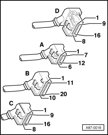
=> "Current Flow Diagrams, Electrical Fault Finding and Fitting Locations" binder

Note:

Only use gold-plated contacts when repairing the contacts in the plug connectors.

If the wiring is OK:

  • ‒ Replace engine control unit => Page 24-12.

Checking idling switch -F60 > < Checking activated charcoal filter system solenoid valve 1 -N80