audi Workshop Repair Guides

Audi Workshop Service and Repair Manuals

Checking control unit power supply > < Checking engine speed sender -G28
MPI fuel injection and ignition system
Checking ignition system
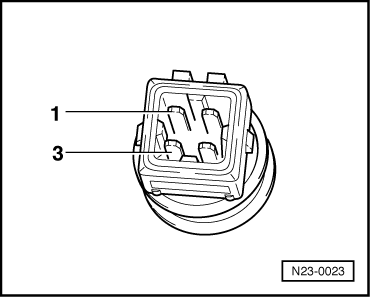
Checking coolant temperature sender -G62
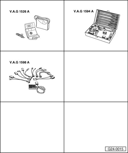
 
G24-0015

Special tools,
testers and equipment required

  • ◆ V.A.G 1526 A
  • ◆ V.A.G 1594 A
  • ◆ V.A.G 1598 A
  • ◆ V.A.G 1598/11

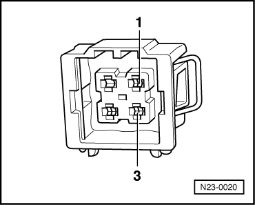
Fitting location => Fitting locations overview, Page 24-6

Note:

Checking operation=> Reading measured value block display group 001, Page 01-100.

 
N23-0023

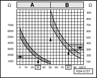
Checking internal resistance

  • ‒ Unplug connector on coolant temperature sender.
  • ‒ → Connect multimeter to contacts 1 and 3 of sender to measure resistance.

Scale A shows resistance values for temperature range 0...50 °C and scale B the values for temperature range 50...100 °C.

 
N24-0157

→ Examples:

  • ◆ 30 °C corresponds to a resistance of 1500...2000 ω
  • ◆ 80 °C corresponds to a resistance of 275...375 ω

If the specifications are not obtained:
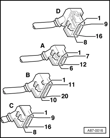
  • ‒ Renew coolant temperature sensor.

Checking wiring

 
A87-0016
  • ‒ → With the ignition switched off, use adapter V.A.G 1598/11 to connect test box V.A.G 1598 A to connector C only of engine control unit (control unit remains disconnected) .
 
N23-0020
  • ‒ → Check for open circuit and short to earth/positive or earth in the following wiring connections:

Connector
Contact

Measure against

Test box V.A.G 1598 A

1

socket 15

3

Engine earth

  • ‒ Rectify short circuit or open circuit if necessary.

=> "Current Flow Diagrams, Electrical Fault Finding and Fitting Locations" binder

  • ‒ If the wiring is OK, fit a new engine control unit => Page 24-20.

Checking control unit power supply > < Checking engine speed sender -G28