audi Workshop Repair Guides

Audi Workshop Service and Repair Manuals

Checking injection quantity, leak tightness and spray pattern of injectors > < Checking system pressure, fuel pressure regulator and holding pressure
MPI fuel injection and ignition system
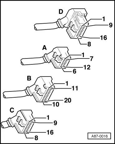
Servicing Multi Point Injection system
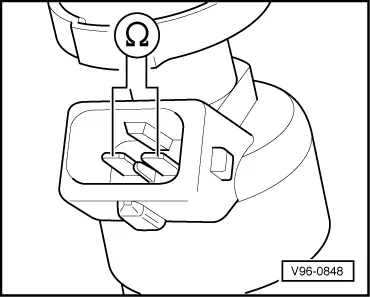
Checking injectors
 
G24-0018

Special tools,
testers and equipment required

  • ◆ V.A.G 1526 A
  • ◆ V.A.G 1527 B
  • ◆ V.A.G 1594 A
  • ◆ V.A.G 1598 A
  • ◆ V.A.G 1598/12
  • ◆ VAS 5051 with VAS 5051/1
  • or
  • ◆ V.A.G 1551 with V.A.G 1551/3 A

Checking internal resistance

  • ‒ Unplug connector on injector to be checked.
 
V96-0848
  • ‒ → Connect multimeter to injector to measure resistance
    • ‒ Specification
      Bosch injector: 15 ... 17 ω
      Siemens injector: 13,5 ... 15,5 ω

If the specification is not obtained:

  • ‒ Renew injector.

Checking power supply

Test requirements:

  • ● Fuel pump relay OK; checking .
 
A97-0022
  • ● → Fuse S234 OK (in fuse holder, position 34).
  • ‒ Unplug connector on injector to be checked.
 
V96-0749
  • ‒ → Connect voltage tester V.A.G 1527 B as follows:

Injector connector
Contact

Measure against

1

Engine earth

  • ‒ Start final control diagnosis and actuate fuel pump relay -J17.
    • ‒ The LED should light up.

If the LED does not light up:

  • ‒ Check wiring from contact 1 via fuse S234 (in fuse holder, position 34) to fuel pump relay:

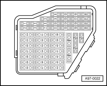
=> "Current Flow Diagrams, Electrical Fault Finding and Fitting Locations" binder

Checking activation

  • ‒ Unplug connector on injector to be checked.
 
V96-0749
  • ‒ → Connect voltage tester V.A.G 1527 B as follows:

Injector connector
Contact

Measure against

2

Battery positive

  • ‒ Operate the starter briefly (the engine may start).
    • ‒ The LED should flash.

If the LED lamp does not flash:

  • ‒ Check wiring =>, Page 24-36

If the LED does not flash for any of the injectors:
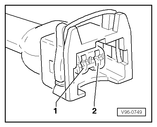
  • ‒ Check the power supply to the engine control unit => Page 28-31.

Checking wiring

  • ‒ Unplug connector on injector to be checked.
 
A87-0016
  • ‒ → With the ignition switched off, use adapter V.A.G 1598/12 to connect test box V.A.G 1598 A to connector D only of engine control unit (control unit remains disconnected) => Page 24-17.
 
V96-0749
  • ‒ → Check for open circuit and short to earth/positive or earth in the following wiring connections:

Cylinder

Injector connector
Contact

Test box V.A.G 1598 A
Socket

1

2

4

2

2

5

3

2

6

4

2

9

5

2

10

6

2

13

  • ‒ Rectify short circuit or open circuit if necessary.

=> "Current Flow Diagrams, Electrical Fault Finding and Fitting Locations" binder

Checking injection quantity, leak tightness and spray pattern of injectors > < Checking system pressure, fuel pressure regulator and holding pressure