audi Workshop Repair Guides

Audi Workshop Service and Repair Manuals

Checking control unit voltage supply > < Checking engine speed sender
Simos injection and ignition system (4-cylinder)
Testing ignition system
Testing coolant temperature sender (version with square connector)

Notes:

  • ◆ Testing sender with oval connector
  • ◆ For testing the operation of the coolant temperature sender, see also "Reading measured value block", Display Group 01, display zone 2.
  • ◆ Fitting location of coolant temperature sender
    .
 
N23-0023
  • ‒ Unplug connector on coolant temperature sender.
  • ‒ → Test resistance between contact 1 (earth) and contact 3 (signal) on sender.
 
N24-0157

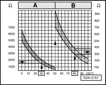
Scale A shows resistance values for temperature range 0...50 °C and scale B the values for temperature range 50...100 °C.

Examples:

  • ◆ 30 °C corresponds to a resistance from 1500...2000 ω
  • ◆ 80 °C corresponds to a resistance from 275...375 ω
  • ‒ If the value does not match the specification, fit a new sender.

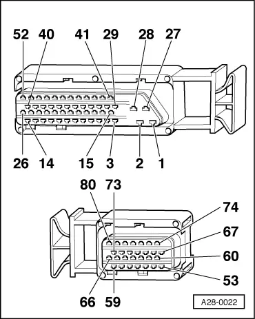
If the value does match the specification, test the wiring between the sender and the engine control unit as follows:

 
N23-0020
  • ‒ Connect test box V.A.G 1598/22 to the wiring harness for the engine control unit.
    => Page 24-13
  • ‒ → Test for open circuit in earth wire between contact 3 on coolant temperature sender connector and socket 67 on test box.

Specification: max. 1 ω.

  • ‒ Test for open circuit in signal wire between contact 1 on coolant temperature sender connector and socket 53 on test box.

Specification: max. 1 ω.

  • ‒ Test for short circuits between the two wires.
 
A28-0022
  • ‒ → If values do not match specifications, rectify short circuits or open circuits in wiring between coolant temperature sender connector and control unit connector.

Contact on
sender connector

Contact on control unit connector or test box

1
3

53
67

  • ‒ If there are no short circuits or open circuits and the coolant temperature sender is OK, fit a new engine control unit.
    => Page 24-15

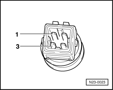
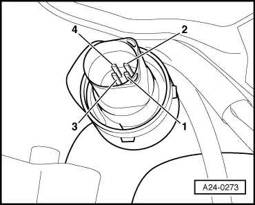
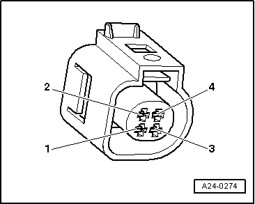
Testing coolant temperature sender with oval connector

Notes:

  • ◆ For testing the operation of the coolant temperature sender, see also "Reading measured value block", Display Group 01, display zone 2.
  • ◆ Fitting location of coolant temperature sender
    => Page 24-5.
  • ‒ Unplug connector from coolant temperature sender.
 
A24-0273
  • ‒ → Connect multimeter (resistance test range)between contacts 3 and 4 on sender.

Scale A shows resistance values for temperature range 0...50°C and scale B the values for temperature range 50...100°C.

 
N24-0157

→ Examples:

  • ◆ 30 °C corresponds to a resistance from 1500...2000 ω
  • ◆ 80°Ccorresponds to a resistance from275...375ω

If the value does not match the specification:

  • ‒ Renew coolant temperature sender
  • ‒ Connect testbox V.A.G 1598/22 to wiring harness for engine control unit.
 
A24-0274
  • ‒ → Test the following wiring connections for open circuit and short circuit to earth or positive:

Connector
contact

Test box V.A.G 1598/22
socket

3

67

4 (signal)

53

  • ‒ Test for short circuits between the two wires.
  • ‒ Repair open circuit or short circuit in wiring as required.

If wiring is OK:

  • ‒ Renew engine control unit.

Checking control unit voltage supply > < Checking engine speed sender