
A4 Mk1
|
Testing auxiliary signals
Testing data exchange between engine control unit / ABS control unit / gearbox control unit
Notes:
Testing bus system If the fault table instructs you to test the data exchange between the engine control unit, gearbox control unit and ABS control unit:
=> Automatic gearbox; Repair group 01; Performing self-diagnosis
=> Running gear, Front-wheel drive and 4WD; Repair group 01; Self-diagnosis, Electrical check If faults have been stored relating to the "Data bus drive" or to data transmission: "No message from ...."
=> Current flow diagrams, Electrical fault finding and Fitting locations
If there are three or more control units in the vehicle linked via a "two-wire data bus system", the following systematic method is recommended when tracing faults:
This will help to localise a fault in the wiring. |
 |
|||||||||
|
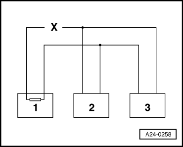
Example 1: From the faults present in the fault memories, you can see that control unit 1 has no connection to control units 2 or 3.
=> Current flow diagrams, Electrical fault finding and Fitting locations
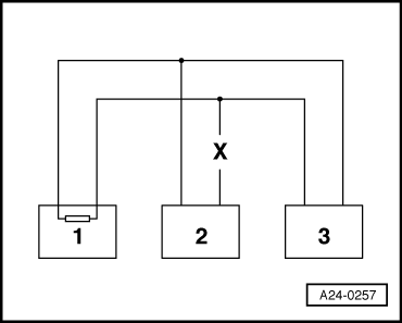
Example 2: |
 |
|||||||||
|
From the faults present in the fault memories, you can see that control unit 2 has no connection to control units 1 or 3.
=> Current flow diagrams, Electrical fault finding and Fitting locations
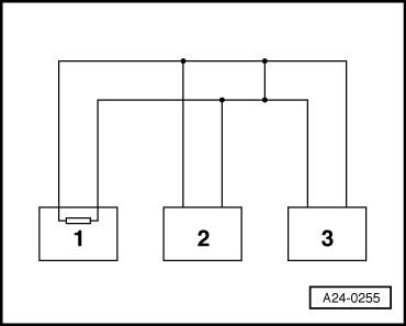
Example 3: From the faults present in the fault memories, you can see that none of the control units are able to transmit or receive signals. |
 |
|||||||||
=> Current flow diagrams, Electrical fault finding and Fitting locations |
 |
|
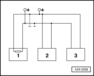
If the cause of the fault "Data bus drive defective" cannot be found in the data bus wires, check whether one of the control units is causing the fault. At this stage all the control units which communicate via the CAN data bus are disconnected. The ignition is switched off.
|