audi Workshop Repair Guides

Audi Workshop Service and Repair Manuals

Servicing intake manifold flap > < Rules for cleanliness
TDI® diesel direct injection and glow plug system (4-cyl. unit injector)
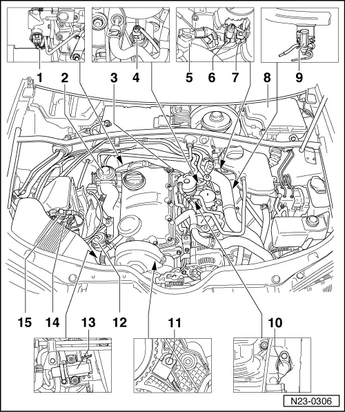
Servicing diesel direct injection system
Fitting locations overview
 
N23-0306

Note:

Some components are located under the engine cover. Removing

=>Fig.23-7.

  • Accelerator pedal position sender -G79
    • ◆ Fitting location
      => Fig.23-7
  • Brake light switch -F and brake pedal switch -F47
    • ◆ Fitting location
      => Fig.23-8
  • Clutch pedal switch -F36
    • ◆ Fitting location
      => Fig.23-8
  • Relay in electronics box in plenum chamber
    • ◆ Fitting locations
      =>Fig. 23-8
 
N23-0306
  • Coolant temperature sender -G62
  • Mechanical exhaust gas recirculation valve
    • ◆ With intake manifold flap
  • Connector
    • ◆ For unit injector
      -N240...243
  • Fuel temperature sender
    -G81
  • Intake manifold pressure sender -G71 with intake manifold temperature sender -G72
  • Connector
    • ◆ For engine speed sender -G28
  • Connector
    • ◆ For Hall sender -G40 for camshaft position
 
N23-0306
  • Diesel direct injection system control unit -J248
    • ◆ With altitude sender -F96
    • ◆ Renewing => Page 23-40
  • Exhaust gas recirculation valve 1 -N18
  • Engine speed sender -G28
  • Hall sender -G40
    • ◆ For camshaft position
  • Pressure unit for charge pressure control
  • Charge pressure control valve -N75 (solenoid valve)
  • Air mass meter -G70
  • Intake manifold flap change-over valve -N239
 
A10-0659

→ Fig.1    Removing engine cover

  • ‒ Pull out oil dipstick -1- from dipstick tube.
  • ‒ Unclip protecting covers.
  • ‒ Unscrew nuts -arrows- and remove engine cover.
  • ‒ Remove noise insulation lying underneath.
  • ‒ Insert dipstick into dipstick tube.
 
A24-0204

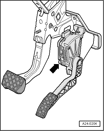
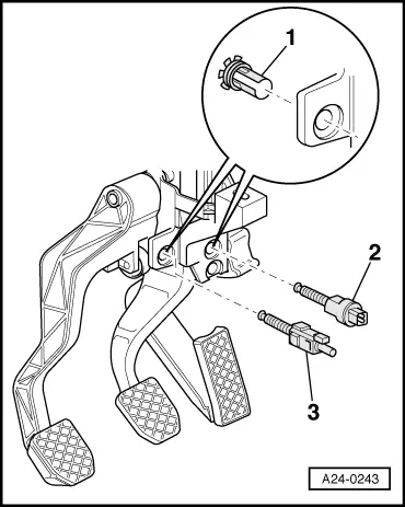
→ Fig.2    Fitting location of accelerator position sender -G79

 
A24-0243

→ Fig.3    Fitting location of brake light switch -F, brake pedal switch -F47 and clutch pedal switch -F36

  •     1 -    Clip
  •     2 -    Brake light switch -F, brake pedal switch -F47
  •     3 -    Clutch pedal switch -F36

Note:

To ensure a secure fitting, the switches may be installed only once.

Adjusting switch:

=> Brake system; Repair group 46

 
A97-0131

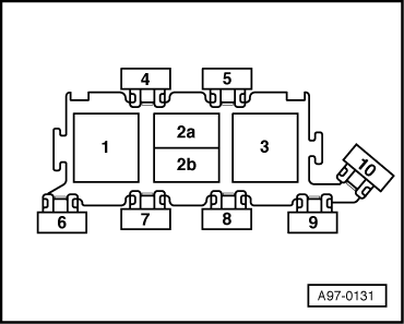
→ Fig.4    Fitting locations: relays in electronics box in plenum chamber

  •     1 -    High heat output relay -J360
  •     2a -    Low heat output relay -J359
  •     3 -    Voltage supply relay (terminal 30) -J317

Servicing intake manifold flap > < Rules for cleanliness