-
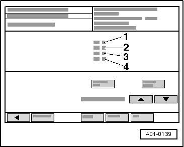
‒ Select "Read data block", Display Group 018, engine idling
→ Display on VAS 5051:
-
‒ Specification: "0" in all 4 display zones for correct control
- Press the ◂ button to exit from the function "08 - Read data block".
- Select diagnosis function "06 - End output".
If the display shows a reading other than "0".
Checking activation
-
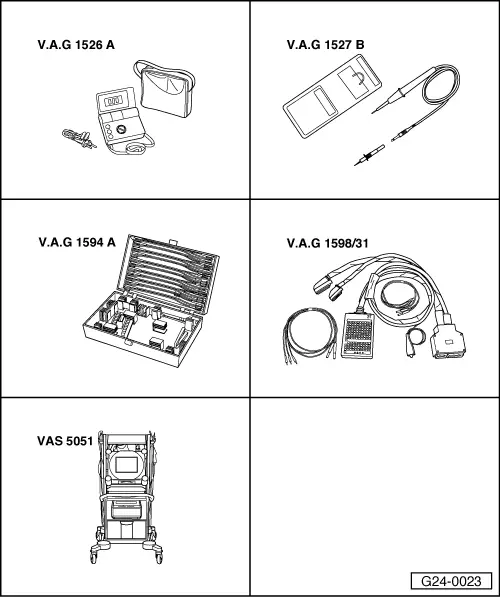
‒ Connect test box V.A.G 1598/31 to wiring harness for engine control unit and to engine control unit => Page 23-37.
-
‒ Connect voltage tester V.A.G 1527 B as follows:
-
‒ Operate starter briefly.
|
|
|---|
|
Test box V.A.G 1598/31
Socket
|
Specification
|
|
114 + 116
|
LED should flash
|
|
114 + 117
|
LED should flash
|
|
114 + 118
|
LED should flash
|
|
114 + 121
|
LED should flash
|
If the specifications are not obtained:
-
‒ Test the wiring => Page 23-25.
If the specifications are obtained:
Testing internal resistance
-
‒ Connect test box V.A.G 1598/31 to wiring harness for engine control unit. Do not connect to the engine control unit itself.
=> Page 23-37.
-
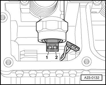
‒ Connect multimeter (resistance test range) as follows:
|
|
|---|
|
Test box V.A.G 1598/31
Socket
|
Specification
|
|
114 + 116
|
approx. 0.5 ω
|
|
114 + 117
|
approx. 0.5 ω
|
|
114 + 118
|
approx. 0.5 ω
|
|
114 + 121
|
approx. 0.5 ω
|
Note:
The specification of approx 0.5ωapplies to a measurement taken directly at the solenoid valve of the unit injector. With the measuring method used here, the wiring resistance has to be added to this figure, so that the reading will always be 0.3 ... 0.5 ω above the specified value.
If the specification is exceeded considerably or if the reading is 0 ω or ∞ ω::
-
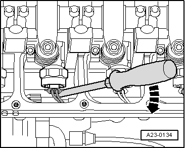
‒ Remove cylinder head cover
=> 4-Cyl diesel direct injection engine (TDI); Repair group 15; Removing and installing cylinder head; Removing and installing cylinder head cover
|