audi Workshop Repair Guides

Audi Workshop Service and Repair Manuals

Checking Hall sender for camshaft position -G40 > < Testing fuel temperature sender -G81
TDI® diesel direct injection and glow plug system (4-cyl. unit injector)
Testing control unit input values
Testing air mass meter -G70

The air mass meter signal is used by the control unit to calculate the quantity injected and to control the required exhaust gas recirculation. The smaller the signal from air mass meter the smaller the quantity of fuel injected.

Test sequence

Warning

Observe safety precautions => Page 01-1.
 
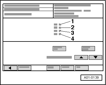
A01-0139
  • ‒ Read measured value block, Display Group 010, engine running at idling speed => Page 01-104.

→ Display on VAS 5051:

  • ‒ Check display in display zone -1-.
    • ‒ Specification: 230 ... 420 mg/stroke

If the specification is not obtained:

  • ‒ Check exhaust gas recirculation:

=> 4-Cylinder TDI engine, Mechanics; Repair group 26; Exhaust gas recirculation system; Checking exhaust gas recirculation

If the specification is obtained:

  • ‒ Accelerate from 2000 rpm at full throttle (without kick-down) in third gear (or with selector lever at position 2), and watch rev counter.
  • ‒ Print out the screen content or self-diagnosis log with engine speed at approx. 3000 rpm. The accelerator pedal must be fully depressed when the print-out is made.
 
A01-0139

→ Display on VAS 5051:

  • ‒ Check readout in display zone -4-.
    • ‒ Specification: 100 % (accelerator position)
  • ‒ Repeat test and accelerate vehicle at full throttle.
  • ‒ Check display in display zone -1-.
    • ‒ Specification: > 850 mg/stoke (intake air mass)
  • ‒ Press the ◂ button to exit from the function "08 - Read data block".
  • ‒ Select diagnosis function "06 - End output".
  • ‒ Switch off ignition.

If the specification is not obtained:

  • ‒ Fit a new air mass meter -G70.
 
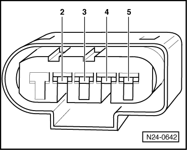
N24-0642

If a constant 539 mg/H (predetermined substitute value) is displayed in display zone 1.

Checking voltage supply

  • ‒ Unplug connector for air mass meter -G70
    =>Fitting locations overview, Page23-6, Item 14.
  • ‒ → Connect multimeter (voltage measurement range) as follows:
  • ‒ Switch on ignition.

Connector
Contact

Specification

2 + earth

approx. battery voltage

2 + 3

approx. battery voltage

4 + earth

approx. 5 V

3 + 4

approx. 5 V

 
N24-0642

If the specifications are not obtained:

Checking wiring connections

  • ‒ Connect test box V.A.G 1598/31 to wiring harness for engine control unit. Do not connect to the engine control unit itself.
    => Page 23-37.
  • ‒ → Test for open circuit and short to positive or earth in the following wiring connections:

Connector
Contact

Test box V.A.G 1598/31
Socket

3

49

4

30

5

68

  • ‒ Rectify any open/short circuit as necessary.

If no fault is found:

  • ‒ Fit a new engine control unit => Page 23-40.

Checking Hall sender for camshaft position -G40 > < Testing fuel temperature sender -G81