audi Workshop Repair Guides

Audi Workshop Service and Repair Manuals

Testing coolant temperature sender -G62 > < Testing engine speed sender -G28
TDI® diesel direct injection and glow plug system (4-cyl. unit injector)
Testing control unit input values
Testing intake manifold pressure sender -G71 and altitude sender -F96

The altitude sender is located in the Diesel direct injection system control unit. The intake manifold pressure sender is a separate component and is located together with the intake manifold temperature sender in a housing on intake manifold.

 
W00-0565

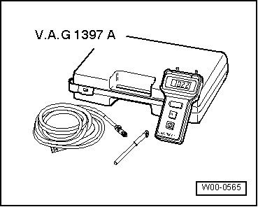
Special tools and workshop equipment required

  • ◆ Turbocharger tester V.A.G 1397 A

Note:

The turbocharger test unit is required to provide an independent figure for comparison. The turbocharger test unit must be set to measuring range I (absolute pressure). A barometer can be used instead.

 
A01-0139

Test sequence

  • ‒ Read data block, Display group 010, engine not running
    => Page 01-104.

→ Display on VAS 5051:

  • ‒ Observe the readouts in display zone -2- (altitude sender -F96) and display zone -3- (intake manifold pressure sender -G71).
    • ‒ Specification: The pressures should be the same.
      Tolerance: ± 30 mbar

If value in display zone 2 deviates:

  • ‒ Fit a new engine control unit => Page 23-40.
 
A21-0154

Value in display zone 3 deviates:

  • ‒ Start engine and run at idling speed.
  • ‒ → Unplug connector at intake manifold pressure sender -G71 -arrow-.
 
A01-0139
  • ‒ Read measured value block, Display Group 010, engine running at idling speed => Page 01-104.

→ Display on VAS 5051:

  • ‒ Observe figures in display zone -3- (intake manifold pressure sender -G71).
    • ‒ Specification: displayed reading should decrease continuously until it equals value of altitude sender (display zone 2)
  • ‒ Press the ◂ button to exit from the function "08 - Read data block".
  • ‒ Select diagnosis function "06 - End output".

If the specification is obtained:

  • ‒ Renew intake manifold pressure sender with intake manifold temperature sender.
 
A24-0094

If the specification is not obtained:

Checking wiring connections

  • ‒ Connect test box V.A.G 1598/31 to wiring harness for engine control unit. Do not connect to the engine control unit itself.
    => Page 23-37.
  • ‒ → Test for open circuit and short to positive or earth in the following wiring connections:

Connector
Contact

Test box V.A.G 1598/31
Socket

1

52

3

31

4

71

  • ‒ Rectify any open/short circuit as necessary.

If no fault is found:

  • ‒ Fit a new engine control unit => Page 23-40.

Testing coolant temperature sender -G62 > < Testing engine speed sender -G28