| –
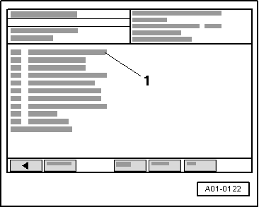
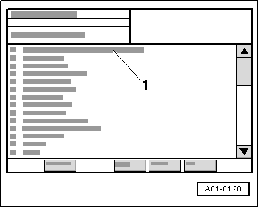
| From list -1- select relevant vehicle system. |
| –
| Interrogate and erase fault memory of control unit just connected. |
| –
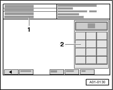
| Select diagnosis function “End output” from the menu -1-. |
| –
| Switch ignition off and on again. |
| –
| Leave ignition switched on for 10 seconds. Then use fault reader to read out fault memory of control unit just connected. |
| –
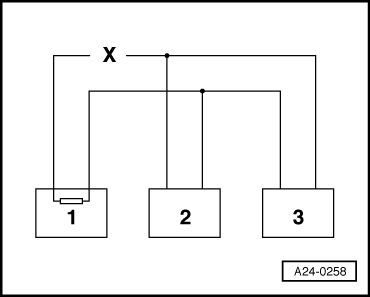
| If the fault “Drive train data bus defective” is now indicated, replace the control unit which has just been connected. |
| –
| If the fault “Drive train data bus defective” is not indicated, connect the next control unit, and repeat the above procedure. |
|
|
|

 Note
Note