audi Workshop Repair Guides

Audi Workshop Service and Repair Manuals

Checking variable intake manifold flap changeover valve N239 > < Checking clutch pedal switch F36
Checking accelerator pedal position senderG79
Checking accelerator pedal position sender -G79-
The accelerator pedal position sender -G79- is located on the accelerator pedal and passes the driver's requirement (pedal position) on to the control unit.
–  Switch on ignition.
–  Read measured value block, Display group 02, engine not running
–  Check display in display zone 2 (accelerator pedal position).
t  Specification: 0.0 % (accelerator pedal not depressed)
–  Check display in display zone 3.
t  Specification: 0 01 00 (Accelerator pedal not depressed) 0 00 00 (Accelerator pedal depressed)
–  Press accelerator pedal down slowly.
t  Specification: the value in display zone 2 should increase steadily to 100 % (accelerator pedal fully depressed).
On vehicles with an automatic gearbox the kickdown switch pressure point must be distinctly felt before the full throttle stop position is reached.
If the final specification is not obtained:
–  Adjust accelerator position sender → Rep. Gr.20
If the display does not change or only changes irregularly:
–  Switch off ignition.
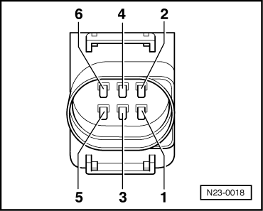
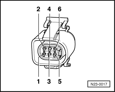
–  Unplug connector from accelerator pedal position sender -G79-
   
–  Connect hand-held multimeter (resistance test range) between the following contacts on the connector:
  N23-0018
Accelerator pedalContactsSpecification
Not depressed1 + 30.8...1.4 kΩ
Not depressed2 + 30.8...1.4 kΩ
Not depressed4 + 60.8...1.2 kΩ
Pressed infinite Ω
Only on vehicles with automatic gearbox:
Not depressed5 + 6infinite Ω
Fully depressed 0.8...1.2 kΩ

If specification is not obtained:
–  Renew accelerator pedal position sender -G79-.
If specification is obtained:
–  Connect test adapter -V.A.G 1598/30- or -V.A.G 1598/31- to wiring harness for engine control unit. Do not connect engine control unit → Chapter.
   
Check the following wiring connections for open circuits and short to positive or earth.
  N23-0017
6-pin connector on wiring harness, contact-V.A.G 1598/30-, socket-V.A.G 1598/31-, socket
14/0869
24/0912
34/0750
44/1370
64/1251
Only on vehicles with automatic gearbox:
54/3463

Resistance in wiring: max. 1.5 Ω
–  Rectify open circuit or short circuit in wiring as necessary → Current flow diagrams, Electrical fault finding and Fitting locations.
   

Checking variable intake manifold flap changeover valve N239 > < Checking clutch pedal switch F36