audi Workshop Repair Guides

Audi Workshop Service and Repair Manuals

Checking injection pump > < Activating/deactivating cruise control system
Checking voltage supply for diesel direct injection system
The injection system receives its power supply via the diesel direct injection system relay -J322-.
To enable the diesel direct injection system relay -J322- to close, there must be voltage (terminal 15) at the diesel direct injection system control unit. In other words, the diesel direct injection system relay -J322- can only receive an earth connection (via the diesel direct injection system control unit) when voltage is applied to the control unit via terminal 15.
  Note
   
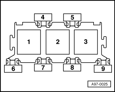
The diesel direct injection system relay -J322- is located in the electronics box in the plenum chamber (relay and fuse carrier, relay position 3).
Test condition
l  Battery voltage OK
Checking voltage supply (terminal 15)
–  Connect test adapter -V.A.G 1598/30- or -V.A.G 1598/31- to wiring harness for engine control unit. Do not connect engine control unit → Chapter.
–  Switch on ignition.
–  Connect multimeter (voltage test range) between the following contacts on the test adapter:
  A97-0025
-V.A.G 1598/30-, socket-V.A.G 1598/31-, socketSpecification
4/26 + earth37 + earthapprox. battery voltage

If specification is not obtained:
–  Check the wiring → Current flow diagrams, Electrical fault finding and Fitting locations.
Checking earth switching for diesel direct injection system relay -J322-
Test condition
l  Battery voltage OK
l  Terminal 15 voltage supply OK
l  Engine control unit connected
   
–  Switch on ignition. Specification: diesel direct injection system relay -J322- should pick up. (Relay is located in relay and fuse holder in electronics box in plenum chamber, relay position 3).
  Note
The clicking of the relay is difficult to hear and is therefore best checked by touching the relay.
If specification is not obtained:
–  Switch off ignition.
–  Connect test adapter -V.A.G 1598/30- or -V.A.G 1598/31- to wiring harness for engine control unit. Do not connect engine control unit → Chapter.
–  Using a test lead from auxiliary measuring set -V.A.G 1594C-, connect together the following sockets on the test adapter.
  A97-0025
-V.A.G 1598/30-, socket-V.A.G 1598/31-, socket
1/09 + 1/0618 + 4

   
Specification: diesel direct injection system relay -J322- should pick up. (Relay is located in relay and fuse holder in electronics box in plenum chamber, relay position 3).
If the relay picks up now, but not when the control unit is connected:
–  Renew diesel direct injection system control unit.
If the relay does not pick up:
–  Switch off ignition.
  A97-0025
–  Unplug diesel direct injection system relay -J322- from relay socket (relay position 3 on relay and fuse holder in electronics box).
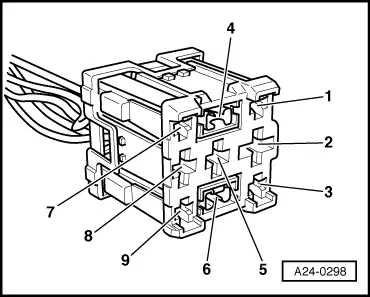
Check for short to positive/negative and open circuit in the following wiring.
  A24-0298
Electronics box, relay socket 3, contact-V.A.G 1598/30-, socket-V.A.G 1598/31-, socket
41/0918

–  Rectify open circuit or short circuit in wiring as necessary → Current flow diagrams, Electrical fault finding and Fitting locations.
Checking voltage supply (terminal 30)
Test condition
l  Battery voltage OK
l  Terminal 15 voltage supply OK
l  Switched earth connection for diesel direct injection system relay -J322- okay
–  Switch off ignition.
   
–  Unplug diesel direct injection system relay -J322- from relay socket (relay position 3 on relay and fuse holder in electronics box in plenum chamber).
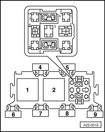
–  Connect hand-held multimeter (voltage test range) between the following contacts on the relay socket:
  A23-0019
Electronics box in plenum chamber, relay socket 3, contactSpecification
2 + earthapprox. battery voltage

If specification is not obtained:
–  Check the wiring → Current flow diagrams, Electrical fault finding and Fitting locations.
If specification is obtained:
   
–  Refit relay in relay socket (relay position 3 on relay and fuse carrier in electronics box in plenum chamber).
–  Unplug connector from injection pump.
–  Connect test adapter -V.A.G 1598/30- or -V.A.G 1598/31- to wiring harness for engine control unit. Do not connect engine control unit → Chapter.
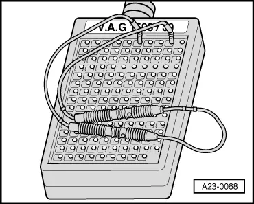
–  Using a test lead from auxiliary measuring set -V.A.G 1594C-, connect together the following sockets on the test adapter.
  A23-0068
-V.A.G 1598/30-, socket-V.A.G 1598/31-, socket
1/09 + 1/0618 + 4

–  Connect multimeter (voltage test range) between the following contacts on the test adapter:
   
-V.A.G 1598/30-, socket-V.A.G 1598/31-, socketSpecification
1/01 + 1/041 + 4approx. battery voltage
1/01 + 1/052 + 4approx. battery voltage
1/01 + 1/061 + 5approx. battery voltage
1/08 + 1/042 + 5approx. battery voltage
1/08 + 1/05 approx. battery voltage
1/08 + 1/06 approx. battery voltage

   
–  Connect hand-held multimeter (voltage test range) between the following contacts on the wiring harness connector:
  A23-0055
9-pin connector on wiring harness, contactSpecification
7 + 6approx. battery voltage

If the specifications are not obtained:
–  Check the wiring → Current flow diagrams, Electrical fault finding and Fitting locations.
   

Checking injection pump > < Activating/deactivating cruise control system