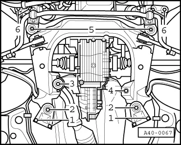
audi Workshop Repair Guides

Audi Workshop Service and Repair Manuals

Removing and installing lower cross-piece > < Subframe
Running gear, Front-wheel drive and four-wheel drive
Subframe
Removing and installing subframe

Special tools and workshop equipment required

  • ◆ 10-222 A Support bar
  • ◆ 10-222 A/1 Frame
  • ◆ 3393 Test bars
  • ◆ V.A.G 1331 Torque wrench
  • ◆ V.A.G 1332 Torque wrench
  • ◆ V.A.G 1383 A Engine/gearbox lifter
 
A40-0066

Removing

  • ‒ → Support engine with support bar.
 
V44-0408
  • ‒ → Detach wheel trim. In the case of light alloy wheels, use puller from vehicle tool kit or suction grip -3208- to remove trim cap.
  • ‒ Remove wheels.
  • ‒ Remove noise insulation.

 
A40-0125
  • ‒ → Before unfastening subframe, use test bar 3393 to check whether holes -1- and -2- coincide.

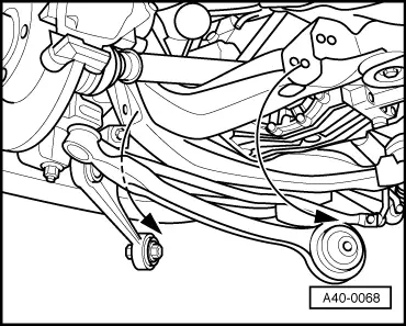
If this is not the case, wheel alignment must be performed after installing subframe.

To avoid damaging joints of lower links provide support, e.g. using V.A.G 1383-A (engine and gearbox lifter), to guard against excessive rebound.

 
A40-0071
  • ‒ → Unscrew hexagon nuts -3-.
  • ‒ Slacken off hexagon bolt -1- for attaching guide link to subframe.

 
A40-0067
  • ‒ → Screw out hexagon bolts -1-.
  • ‒ Slacken off hexagon bolts -2- and lower subframe at rear.

Note:

To excessive bending of pin-end joints of track control and guide links, they are to be attached to body with wire or the like.

  • ‒ Pull out hexagon bolts of guide links.
  • ‒ Pull guide link out of subframe.
 
A40-0071
  • ‒ → Screw out hexagon bolt -5-.

For vehicles with headlight range control, refer to .

  • ‒ Unfasten hexagon nut -2- for attaching track control link to subframe and take out hexagon bolt.
  • ‒ Pull wire of ABS speed sensor out of holder at brake caliper.

 
A40-0068
  • ‒ → Pull track control link out of subframe.
 
A40-0069
  • ‒ → Unscrew hexagon nuts -3- and -4-.
  • ‒ Unscrew hexagon bolts -5-.
  • ‒ Slacken off hexagon bolts -6- until subframe can be taken out.

Installing

Note:

Always replace bolts and nuts.

 
A40-0069
  • ‒ → Insert subframe and fit hexagon bolts -5- and -6-.

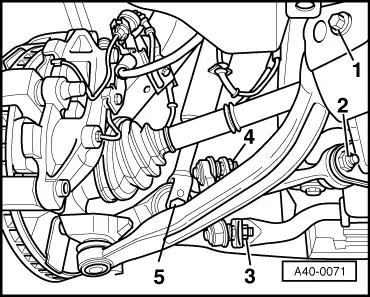
Note:

Heed installation position of suspension strut/track control link bolted joint .

  • ‒ Fit hexagon bolt for suspension strut at track control link.
 
A40-0070
  • ‒ → Insert track control and guide links in subframe.
  • ‒ Insert bolts in inner holes -arrows-.
  • ‒ On vehicles with headlight range control, fit connecting link of vehicle level sender at track control link => Page 40-22.

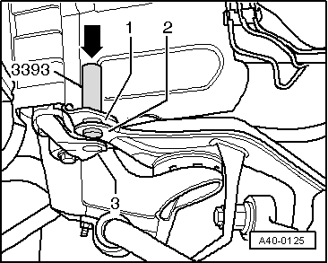
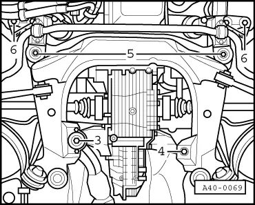
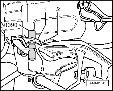
Before tightening, subframe must be located with respect to body using test bar 3393.

 
A40-0126
  • ‒ → Hole -1-, hole -2- of subframe and hole -3- of aluminium bracket must be aligned on both sides.

Note:

This locating procedureprovides a substitute for subsequent wheel alignment:

  • ◆ If only subframe has been removed/installed.
  • ◆ If holes -1- and -2- coincided prior to repair work.
 
A40-0067
  • ‒ → Fit hexagon bolts -1- and -2-.
  • ‒ Fit hexagon nuts -3- and -4-.
  • ‒ Protect hole in body for test bar 3393 against corrosion.

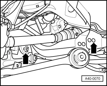
Tightening sequence/tightening torques

Bonded rubber bushes can only be turned to a limited extent. The bolted joints at the suspension links are therefore not to be tightened until the vehicle is standing on the ground.

 
A40-0067
  • ‒ → Tighten hexagon bolts -2- and -5- to 110 Nm and give further 90° turn.
  • ‒ Tighten hexagon bolts -6- to 75 Nm.
  • ‒ Tighten hexagon bolts -1-.
    • Tightening torques:
    • Non-ribbed hexagon bolt: 30 Nm
    • Ribbed hexagon bolt: 75 Nm
  • ‒ Tighten hexagon nuts -3- and -4- to 40 Nm.
  • ‒ Tighten hexagon nuts for track control link to 80 Nm and give further 90° turn.
  • ‒ Tighten hexagon nuts for guide link to 90 Nm and give further 90° turn.

Pay attention to modified connecting links and tightening torques
.

  • ‒ Attach connecting link to anti-roll bar with new ribbed nuts (100 Nm).
  • ‒ Attach suspension strut to track control link (90 Nm).
  • ‒ Insert wire of ABS speed sensor in holder at brake caliper.
  • ‒ Fit and secure wheels => Page 44-1.

Notes:

  • ◆ Wheel alignment is not necessary if subframe was located with respect to body using test bar 3393 prior to removal and assembly (before tightening bolts).
  • ◆ Wheel alignment must be performed if locating procedure was not employed.
  • ‒ Perform wheel alignment => Page 44-13.

Removing and installing lower cross-piece > < Subframe