|
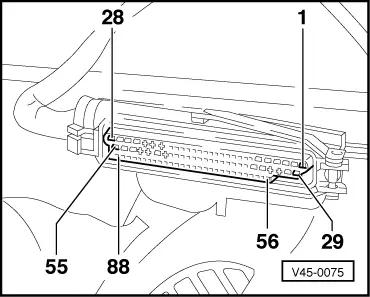
→ Socket designations of test box V.A.G 1598/20 are identical with contact designations on control unit -J104 as well as those on wiring harness connector.
=> Current Flow Diagrams, Electrical Fault-finding and Fitting Locations binder
-
‒ Connect test box V.A.G 1598/20 to multi-pin connector on wiring harness.
Contact assignment of control unit -J104
|
Multi-pin connector on control unit -J104
|
|
|
Contact
|
closed
|
|
Contact
|
|
1
|
=>
|
Voltage supply from terminal 15
TCS/ESP switch
|
-
5
|
|
2
|
=>
|
Voltage supply from terminal 15
Return pump relay -J105
Solenoid valve relay ABS -J106
Steering angle sender -G85; [control unit 8D0 907 389/A/D/E]
Steering angle sender -G85; [control unit 4B0 907 389]
|
86
86
5
3
|
|
3
|
=>
|
Hydraulic unit; actuation of outlet valve, front left -N102
|
15
|
|
4
|
=>
|
Hydraulic unit; actuation of outlet valve, rear right -N135
|
12
|
|
5
|
=>
|
Hydraulic unit; actuation of inlet valve, front left -N101
|
8
|
|
6
|
=>
|
Hydraulic unit; actuation of inlet valve, rear right -N133
|
2
|
|
7
|
=>
|
Return pump relay -J105 (earth)
|
85
|
|
8
|
=>
|
Front left speed sensor -G47
- Vehicles with 4WD
|
-
|
=> Current Flow Diagrams, Electrical Fault-finding and Fitting Locations binder
|
Multi-pin connector on control unit -J104
|
|
|
Contact
|
closed
|
|
Contact
|
|
9
|
=>
|
Front left speed sensor -G47
- Vehicles with FWD
|
-
|
|
10
|
=>
|
Front left speed sensor -G47 (earth)
|
-
|
|
11
|
=>
|
Rear right speed sensor -G44
|
-
|
|
12
|
=>
|
Rear right speed sensor -G44 (earth)
|
-
|
|
13
|
=>
|
Rear left speed sensor -G46
|
|
|
14
|
=>
|
Rear left speed sensor -G46 (earth)
|
-
|
|
15
|
=>
|
Front right speed sensor -G45
|
-
|
|
16
|
=>
|
Front right speed sensor -G45 (earth)
|
-
|
|
17
|
=>
|
Not used
|
-
|
=> Current Flow Diagrams, Electrical Fault-finding and Fitting Locations binder
|
Multi-pin connector on control unit -J104
|
|
|
Contact
|
closed
|
|
Contact
|
|
18
|
=>
|
Lateral acceleration sender -G200; signal wire [control unit 4B0 907 389]
|
2
|
|
18
|
=>
|
Lateral acceleration sender -G200; signal wire (combined sender for yaw rate and lateral acceleration) [control unit 8D0 907 389/A/D/E]
|
4
|
|
19
|
=>
|
Lateral acceleration sender -G200; (earth) [control unit 4B0 907 389]
|
1
|
|
19
|
=>
|
Not used; [control unit 8D0 907 389/A/D/E]
|
-
|
|
20
|
=>
|
Return pump relay -J105
Hydraulic unit; monitoring connection for return pump -V39
|
87
14
|
|
21
|
=>
|
Not used
|
-
|
|
22
|
=>
|
ESP hydraulic pump -V156; voltage supply
|
2
|
|
23
|
=>
|
Not used
|
-
|
|
24
|
=>
|
ESP hydraulic pump -V156; (earth)
|
1
|
=> Current Flow Diagrams, Electrical Fault-finding and Fitting Locations binder
|
Multi-pin connector on control unit -J104
|
|
|
Contact
|
closed
|
|
Contact
|
|
25
|
=>
|
Hydraulic unit; actuation of outlet valve, rear left -N136
|
11
|
|
26
|
=>
|
Hydraulic unit; actuation of inlet valve, front right-N99
|
5
|
|
27
|
=>
|
Not used
|
-
|
|
28
|
=>
|
Earth connection, terminal 31
|
-
|
|
29
|
=>
|
Earth connection, terminal 31
|
-
|
|
30
|
=>
|
Not used
|
-
|
|
31
|
=>
|
Dash panel insert; TCS/ESP-lamp -K86 [control unit 4B0 907 389]
|
=> CFD
|
|
31
|
=>
|
Wheel speed sensor output rear left; [control unit 8D0 907 389/A/D/E]
|
-
|
|
32
|
=>
|
Dash panel insert, ABS/EDL lamp -K47
|
=> CFD
|
|
33
|
=>
|
Not used
|
-
|
=> Current Flow Diagrams, Electrical Fault-finding and Fitting Locations binder
|
Multi-pin connector on control unit -J104
|
|
|
Contact
|
closed
|
|
Contact
|
|
34
|
=>
|
Yaw rate sender -G202; voltage supply; [control unit 4B0 907 389]
|
2
|
|
34
|
=>
|
Yaw rate sender -G202; voltage supply (combined sender for yaw rate and lateral acceleration) [control unit 8D0 907 389/A/D/E]
|
1
|
|
35
|
=>
|
Not used
|
-
|
|
36
|
=>
|
Not used; [control unit 4B0 907 389]
|
-
|
|
36
|
=>
|
Solenoid valve relay -J106 (earth); [control unit 8D0 907 389/A/D/E]
|
85
|
|
37
|
=>
|
Solenoid valve relay -J106 (earth); [control unit 4B0 907 389]
|
85
|
|
37
|
=>
|
Not used; [control unit 8D0 907 389/A/D/E]
|
-
|
|
38
|
=>
|
Not used
|
-
|
|
39
|
=>
|
Not used
|
-
|
=> Current Flow Diagrams, Electrical Fault-finding and Fitting Locations binder
|
Multi-pin connector on control unit -J104
|
|
|
Contact
|
closed
|
|
Contact
|
|
40
|
=>
|
Not used
|
-
|
|
41
|
=>
|
Not used
|
-
|
|
42
|
=>
|
Brake light switch -F; brake test switch
|
4
|
|
43
|
=>
|
Not used
|
-
|
|
44
|
=>
|
TCS/ESP switch
|
6
|
|
45
|
=>
|
Not used
|
-
|
|
46
|
=>
|
Diagnostic connector; K-wire
|
7
|
|
47
|
=>
|
Not used
|
-
|
|
48
|
=>
|
Brake light switch -F; brake light switch
|
2
|
|
49
|
=>
|
Hydraulic unit -N55; actuation of switch valve 1 for ESP -N225
|
7
|
|
50
|
=>
|
Hydraulic unit -N55; actuation of ESP -N226
|
6
|
|
51
|
=>
|
Voltage supply, terminal 30 for ESP hydraulic pump -V156;
|
-
|
=> Current Flow Diagrams, Electrical Fault-finding and Fitting Locations binder
|
Multi-pin connector on control unit -J104
|
|
|
Contact
|
closed
|
|
Contact
|
|
52
|
=>
|
Hydraulic unit -N55; actuation of ESP high-pressure valve 2 -N228
|
4
|
|
53
|
=>
|
Hydraulic unit -N55; actuation of ABS inlet valve rear left -N134
|
3
|
|
54
|
=>
|
Hydraulic unit -N55; actuation of ESP high-pressure valve 1 -N227
|
1
|
|
55
|
=>
|
Hydraulic unit -N55; actuation of outlet valve front right -N100
|
9
|
|
56
|
=>
|
Not available
|
-
|
|
57
|
=>
|
Not available
|
-
|
|
58
|
=>
|
Not available
|
-
|
|
59
|
=>
|
Not available
|
-
|
|
60
|
=>
|
Not available
|
-
|
|
61
|
=>
|
Not used
|
-
|
|
62
|
=>
|
Not used
|
-
|
|
63
|
=>
|
Not used
|
-
|
=> Current Flow Diagrams, Electrical Fault-finding and Fitting Locations binder
|
Multi-pin connector on control unit -J104
|
|
|
Contact
|
closed
|
|
Contact
|
|
64
|
=>
|
CAN bus low; Engine control unit, Gearbox control unit,
Steering angle sender-G85
|
=> CFD
2
|
|
65
|
=>
|
Not used; [control unit 4B0 907 389]
|
-
|
|
65
|
=>
|
CAN bus screen; [control unit 8D0 907 389/A/D/E]
|
-
|
|
66
|
=>
|
CAN bus high (engine control unit, gearbox control unit,
Steering angle sender -G85)
|
=> CFD
3
|
|
67
|
=>
|
Brake pressure sender -G201; (earth) [control unit 4B0 907 389]
|
1
|
|
67
|
=>
|
Brake pressure sender -G201; voltage supply [control unit 4B0 907 389/A/D/E]
|
1
|
|
68
|
=>
|
Brake pressure sender -G201; signal wire
|
2
|
|
69
|
=>
|
Brake pressure sender -G201; voltage supply [control unit 4B0 907 389]
|
3
|
|
69
|
=>
|
Brake pressure sender -G201; (earth) [control unit 8D0 907 389/A/D/E]
|
3
|
=> Current Flow Diagrams, Electrical Fault-finding and Fitting Locations binder
|
Multi-pin connector on control unit -J104
|
|
|
Contact
|
closed
|
|
Contact
|
|
70
|
=>
|
Wheel speed sensor output rear left; [control unit 4B0 907 389]
|
=> CFD
|
|
70
|
=>
|
Dash panel insert; TCS/ESP-lamp -K86; [control unit 8D0 907 389/A/D/E]
|
=> CFD
|
|
71
|
=>
|
Speed sensor output, rear right.
|
=> CFD
|
|
72
|
=>
|
Not used; [control unit 4B0 907 389]
|
-
|
|
72
|
=>
|
Wheel speed sensor output front left; [control unit 8D0 907 389/A/D/E]
|
=> CFD
|
|
73
|
=>
|
Not used; [control unit 4B0 907 389]
|
-
|
|
73
|
=>
|
Wheel speed sensor output front right; [control unit 8D0 907 389/A/D/E]
|
=> CFD
|
|
74
|
=>
|
Not used
|
-
|
|
75
|
=>
|
Lateral acceleration sender -G200; voltage supply,
[control unit 4B0 907 389]
|
3
|
|
75
|
=>
|
Not used; [control unit 8D0 907 389/A/D/E]
|
-
|
|
76
|
=>
|
Handbrake warning switch -F9
|
=> CFD
|
=> Current Flow Diagrams, Electrical Fault-finding and Fitting Locations binder
|
Multi-pin connector on control unit -J104
|
|
|
Contact
|
closed
|
|
Contact
|
|
77
|
=>
|
Yaw rate sender -G202; test signal [control unit 4B0 907 389]
|
5
|
|
77
|
=>
|
Yaw rate sender -G202; test signal (combined sender for yaw rate and lateral acceleration) [control unit 8D0 907 389/A/D/E]
|
3
|
|
78
|
=>
|
Yaw rate sender -G202; reference signal [control unit 4B0 907 389]
|
4
|
|
78
|
=>
|
Yaw rate sender -G202; reference signal (combined sender for yaw rate and lateral acceleration) [control unit 8D0 907 389/A/D/E]
|
5
|
|
79
|
=>
|
Yaw rate sender -G202; signal wire; [control unit 4B0 907 389]
|
3
|
|
79
|
=>
|
Yaw rate sender -G202; signal wire (combined sender for yaw rate and lateral acceleration) [control unit 8D0 907 389/A/D/E]
|
6
|
|
80
|
=>
|
Yaw rate sender -G202; (earth) [control unit 4B0 907 389]
|
1
|
|
80
|
=>
|
Yaw rate sender -G202; (earth) (combined sender for yaw rate and lateral acceleration) [control unit 8D0 907 389/A/D/E]
|
2
|
=> Current Flow Diagrams, Electrical Fault-finding and Fitting Locations binder
|
Multi-pin connector on control unit -J104
|
|
|
Contact
|
closed
|
|
Contact
|
|
81
|
=>
|
Not used
|
-
|
|
82
|
=>
|
Not used
|
-
|
|
83
|
=>
|
Not used
|
-
|
|
84
|
=>
|
Not used
|
-
|
|
85
|
=>
|
Not used
|
-
|
|
86
|
=>
|
Not used; [control unit 4B0 907 389]
|
-
|
|
86
|
=>
|
Dash panel insert, standing time signal; [control unit 8D0 907 389/A/D/E]
|
=> CFD
|
|
87
|
=>
|
Not used
|
-
|
|
88
|
=>
|
Not used
|
-
|
=> Current Flow Diagrams, Electrical Fault-finding and Fitting Locations binder
Notes on fault table
-
◆ The socket descriptions of test box V.A.G 1598 are identical to the contact descriptions of control unit -J104 in the current flow diagram. Incorrect test procedures can cause system damage. Do not make connections between any contacts other than those listed in the test table.
=> Current Flow Diagrams, Electrical Fault-finding and Fitting Locations binder
-
◆ The specified values refer to the readings obtained on tester V.A.G 1526 and are not necessarily applicable to other test units.
-
◆ If the readings obtained do not match the specified values, carry out the fault remedy measures in the right-hand part of the table.
=> Current Flow Diagrams, Electrical Fault-finding and Fitting Locations binder
-
◆ If the specified values are achieved, also check wiring for loose contacts and short circuit to positive and earth. This applies especially to sporadic faults.
-
◆ Use test leads V.A.G 1594 for checking continuity (bridging leads).
-
◆ If the measured figures only differ slightly from the specified values, clean the sockets and plugs of the testers and test leads (with contact spray G 000 700 04) and repeat the check. Before replacing components, check wiring and connections again. This is particularly important if the specification calls for a resistance reading of less than 10 ω.
|