
A4 Mk1
|
ESP, Electronic-Stability-Program Bosch 5.3
Final control diagnosis
Final control diagnosis permits checking of the function of the control elements. The control elements are also called actuators. These are components which actuate the control unit when it responds to the incoming sensor signals, for example solenoid valves, relays and pump motors. Notes: The final control diagnosis only works on vehiclesequipped with a control unit with the numbers 8D0 407 389 A/D/E. Final control diagnosis cannot be performed for control unit no. 4B0 907 389. Final control diagnosis can and is only to be implemented once after switching on ignition. The function of the "final control elements" includes all functions and properties of the final control elements under operating conditions. This means, for example:
Before running a final control diagnosis, it is advisable to ensure that there are no electrical faults in the system you wish to test. This will enable you to recognise any mechanical faults. Perform fault-finding procedure as described on . Are you sure there are no electrical faults in the system? If yes, you will recognise the faults in the mechanics of the individual control elements as soon as the final control diagnosis deviates from its description. In this case, renew the affected component. Final control diagnosis with the Bosch ABS/ESP 5.3 system permits checking of the electrically actuated hydraulic valves and the pump motor in the hydraulic control unit. Notes:
When implementing the final control diagnosis function the individual test steps are shown in the second line of the V.A.G 1551 display. The following abbreviations are used: I = Inlet valve O = Outlet valve FL = front left FR = front right RL = rear left RR = rear right VBAT = Battery voltage applied to valve 0V = No voltage at valve; 0 Volt Locked/free = Wheel condition; must be checked by 2nd mechanic Hydr-P = Hydraulic pump
|
| → Indicated on display: |
|
||
|
| → Indicated on display: |
|
||
|
| → Indicated on display: |
|
||
|
Hydraulic pump ABS-V39 must run. It can be heard. |
 |
|
|
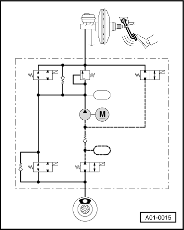
→ When you put your foot on the brake pedal you can feel it vibrating. The brake pedal vibrates because the hydraulic pump generates pressure pulses in the brake pipes. These pressure pulses induce vibrations. These are transferred to the brake pedal and the vibrations can be detected there. The pressure pulses in the brake pipes are not sufficient to lock the wheels. |
|
|
|
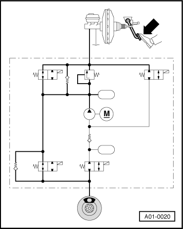
→ The drawing on the left is a schematic diagram of the hydraulic circuit of an ABS/EDL system. This will give a better understanding of the various test steps in the final control diagnosis.
|
| → Indicated on display: |
|
||
|
| → Indicated on display: |
|
||
 |
|
|
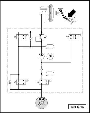
→ When you press the brake pedal, brake fluid pressure will be built up in all four wheel brake cylinders. All four wheels will be locked. This presupposes proper functioning of the mechanical and hydraulic components of the brake system. This means, that the brake master cylinder is able to build up pressure in all wheel brake cylinders and that there are no leaks in the hydraulic connections and pipes. |
|
|
|
If the wheels do not lock, perform a visual inspection of the brake fluid reservoir, the master cylinder, the hydraulic unit and the wheel cylinders. To start with, however, concentrate on the front left wheel. The function of the control elements for this wheel is tested first. Note: This test step in the final control diagnosis corresponds to the "pressure build-up" phase during ABS-controlled braking.
|
| → Indicated on display: |
|
||
 |
|
|
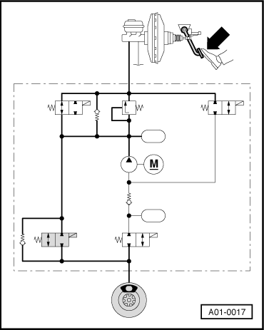
Keep pressing the brake pedal. → The inlet valve is actuated. It interrupts the brake pipe. However, the fluid pressure is still maintained in the wheel cylinder. The front left wheel remains locked. Note: This test step in the final control diagnosis corresponds to the "maintain pressure" phase during ABS-controlled braking.
|
| → Indicated on display: |
|
||
 |
|
|
Keep pressing the brake pedal. The inlet valve and the outlet valve for the front left wheel are activated. The hydraulic pump starts running and reduces the fluid pressure in the wheel cylinder via the open outlet valve. The brake pedal must not give, and should press back harder against your foot. You should now be able to turn the front left wheel. If you cannot turn the wheel, check whether the brake line for the front left wheel is correctly connected. |
|
|
|
If this is the case, this indicates that there is a mechanical fault in one of the valves, providing that there is no electrical fault in the system. Renew the hydraulic control unit. If the brake pedal gives under your foot, this means that the inlet valve or the non-return valve connected in parallel with the inlet valve is leaking. Renew the hydraulic control unit. Note: This test step in the final control diagnosis corresponds to the "pressure reduction" phase during ABS-controlled braking.
|
| → Indicated on display: |
|
||
|
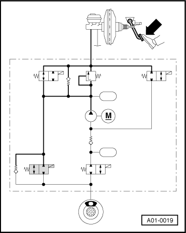
Hydraulic pump ABS -V39 stops running. Keep pressing the brake pedal. Only the inlet valve is now actuated and interrupts the brake pipe. Front left wheel can be turned if inlet valve is not leaking. |
 |
|
|
If wheel cannot be turned, there is a leak either in the inlet valve or in the non-return valve connected in parallel with it. Renew the hydraulic control unit.
|
| → Indicated on display: |
|
||
 |
|
|
Keep pressing the brake pedal. Inlet valve is no longer actuated. It no longer interrupts brake pipe. Brake pedal sags perceptibly. Fluid pressure is built up in front left wheel brake cylinder. Wheel locks.
|
| → Indicated on display: |
|
||
Continue the final control diagnosis in order to check the front right, rear left and rear right wheels in turn. The test steps are the same as for the front left wheel. Thus there are not described in detail. |
| → Indicated on display: |
|
||
|
| → Indicated on display: |
|
||
|
| → Indicated on display: |
|
||
Hydraulic pump ABS-V39 must run. Brake pedal must not give. |
| → Indicated on display: |
|
||
Hydraulic pump ABS -V39 stops running. |
| → Indicated on display: |
|
||
Brake pedal should give perceptibly. |
| → Indicated on display: |
|
||
|
| → Indicated on display: |
|
||
|
| → Indicated on display: |
|
||
|
| → Indicated on display: |
|
||
|
| → Indicated on display: |
|
||
Hydraulic pump ABS-V39 must run. Brake pedal must not give. |
| → Indicated on display: |
|
||
Hydraulic pump ABS -V39 stops running. |
| → Indicated on display: |
|
||
Brake pedal should give perceptibly. |
| → Indicated on display: |
|
||
|
| → Indicated on display: |
|
||
|
| → Indicated on display: |
|
||
 |
|
|
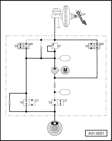
The EDL change-over valve (left) and the EDL inlet valve (right) are actuated. ABS/EDL hydraulic pump -V39 runs for one second. Pump draws brake fluid out of fluid reservoir. The hydraulic pump builds up brake fluid pressure in the EDL controlled wheel brake cylinders. These wheels lock. If this is not the case, this indicates that there is a mechanical fault in one of the valves, provided that there are no electrical faults in the system. Renew the hydraulic control unit.
|
| → Indicated on display: |
|
||
|
The final control diagnosis is complete. The ABS/EDL warning lamp and the brake system warning lamp extinguish.
|
| → Indicated on display: |
|
||
|
Note:
|