
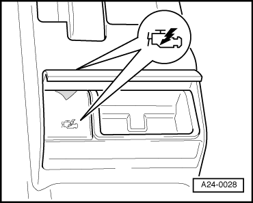
A4 Mk1 ABS and ESP Self-Diagnosis with VAG 1551
|
Self-diagnosis
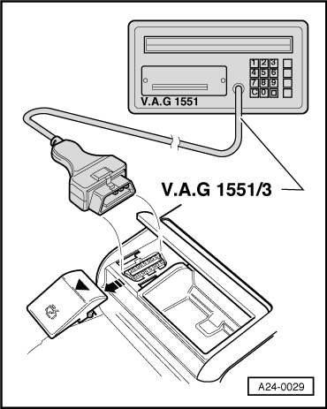
Connecting fault reader V.A.G 1551 and selecting address word
|
 |
|
|
Use can be made of the vehicle diagnostic system tester V.A.G 1552 or the vehicle diagnostic, testing and information system VAS 5051 instead of the fault reader V.A.G 1551. However, with vehicle systems tester V.A.G 1552 there is no option to print out information.
|
 |
|
|
| → Indicated on display: |
|
|||
|
1) displayed alternately Notes:
|
|
|
|
=> Current Flow Diagrams, Electrical Fault-finding and Fitting Locations binder
|
| → Indicated on display: |
|
||
|
Note: The address word selects the control unit of the on-board system that you wish to test with the fault reader. The address word is made up of two digits, which are given in the relevant sections of this Workshop Manual. For example: Press keys 03 to enter the address word for "Brake electronics". |
| → Indicated on display: |
|
||
|
| → Display after address word 03 has been entered: |
|
||
|
Note: If a fault occurs in the communication link between fault reader V.A.G 1551 and the control unit, one of the following four displays will appear. |
| Press the HELP key to obtain a printout of the possible causes of fault. |
|
||
| Check diagnostic wiring ("K" wire). |
|
||
|
=> Current Flow Diagrams, Electrical Fault-finding and Fitting Locations binder
=> Current Flow Diagrams, Electrical Fault-finding and Fitting Locations binder |
| → If this display appears: |
|
||
=> Current Flow Diagrams, Electrical Fault-finding and Fitting Locations binder
|
| → If communication between fault reader and control unit has been established and is functioning properly, display indicates control unit -identification (X), system designation (Y), hardware and software version (Z), coding (V) and workshop code (W). |
|
||
|
Notes:
=> Replacement Parts Catalogue
=> Current Flow Diagrams, Electrical Fault-finding and Fitting Locations binder
|
| → Indicated on display: |
|
||