
A4 Mk1
|
|
|
 Note
Note |
|
|
|
Note |
|
Note
|
|
|
|
|
|
Note
Note
Note
|
|
Note
|
|
| Component | Nm |
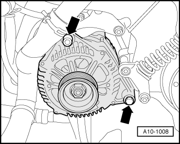
| Alternator to engine | 23 |
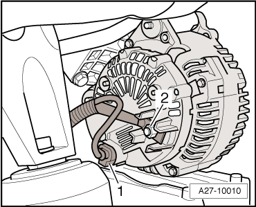
| 30/B+ terminal to alternator | 16 |
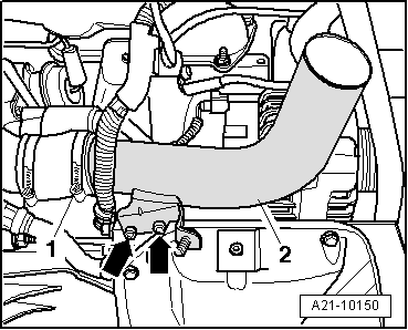
| Air intake pipe to sump (top section) | 10 |
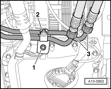
| Bracket for refrigerant line to sump (top section) | 9 |
| Clamp to bracket for refrigerant line | 9 |